This workflow will show you how to model non-rectangular patches in Leica’s Cyclone.
Hint: You can click on any image to see a larger version.
[wptabs style=”wpui-alma” mode=”vertical”] [wptabtitle] THE 2D DRAWING TOOLBAR[/wptabtitle]
[wptabcontent]
Modeling a Non-Rectangular Patch
Quick Discussion on 2D Drawing and Reference Planes
To create a non-rectangular patch, you use the tools on the 2D drawing toolbar. If the drawing toolbar is not enabled, RC anywhere in the Toolbar area and add the Drawing toolbar. As a good rule of thumb, I always dock it on the right side of the screen.
IMPORTANT: All 2D drawings in Cyclone are constrained to a base plane. To view the active reference plane, go to Tools –> Reference Plane –> Show Active Plane. All cyclone projects come with a default XY plane (Z normal) – shown to the below.
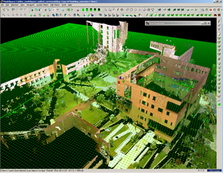 Figure 12: The base XY plane in all Cyclone projects.
You can add numerous reference planes to a project Tools –> Reference Plane –> Add/Edit. You can also move reference planes and assign them to selected objects Select Object -> RC -> Set on Object. If you are not working in a specific coordinate system, it is easiest just to move the active reference plane to the object that you are trying to model.
[/wptabcontent]
[wptabtitle]MODEL A NON-RECTANGULAR PATCH[/wptabtitle]
[wptabcontent]Model a Non Rectangular Patch
To model a non-rectangular patch such as a unique outline of a wall, first fence and create a small patch on the wall. Next, go to Tools –> Reference Plane –> Set on Object to align the reference plane along the same direction as the newly created patch. Select the patch, select ViewPoint –> Align to Selection, this constrains the view to be directly perpendicular to the patch. At this point, it is important not to rotate the view, if necessary choose View –> View Lock –> Rotate.
 Figure 13: (Left) Drawing a small patch along a section of wall and (Right) Aligning the base reference plane to that patch in order to use the 2D drawing tools
Note: viewing orthogonally or perspectively affects visibility and clarity of features; toggle between views with hot key ‘o’.
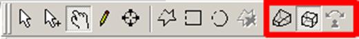 Figure 14: Mode Toolbar shows whether current view is orthogonal or perspective
Next choose the appropriate 2D drawing tool, in this case Draw Polygon tool ->Trace the feature of interest -> Accept/Create the drawing by either clicking the green check button at the top of the Drawing Toolbar or RC -> Create. The 2D sketch should turn bright green with orange handle at the intersections. Edit the sketch as needed. Next to create a patch from the 2D sketch, select the sketch -> Create Object –> From Curves –> Patch.
 Figure 15: (Left) 2D Curve sketched on building feature profile (Right) Patch fit to the curve
[/wptabcontent]
[wptabtitle]You have Finished![/wptabtitle]
[wptabcontent]You have finished the Leica Cyclone 7.0: Introduction to Modeling workflow![/wptabcontent][/wptabs]