This series will show you advanced modeling building modeling techniques using Leica’s Cyclone.
Hint: You can click on any image to see a larger version.
As objects become more complex, using layers (Shift + L) becomes essential to organizing and controlling the model space.
[wptabs style=”wpui-alma” mode=”vertical”] [wptabtitle] CHOOSE YOUR MODELING METHOD[/wptabtitle]
[wptabcontent]
As noted, it is best to model features in individual ModelSpaces, re-inserting them into the original ModelSpace upon completion. Often features, such as windows, will repeat on structures or sites. Whether each feature is modeled individually or modeled once and then repeated depends on the discretion of the user and the nature of the subject. New, modern structures (such as office buildings) are well-suited to modeling features once and repeating them as they often utilize standardized materials and building methods. Older and/or deteriorating structures/sites are better-suited to modeling features individually as time, movement, and building methods often result in more organic, unique features. As always, the method of modeling depends on the subject and the user’s intentions.
[/wptabcontent]
[wptabtitle] COPY WORKING AREA[/wptabtitle] [wptabcontent]
1. Copy working area to new Working ModelSpace (for example, you may be modeling an entire building but at the current stage, you are inserting a repeating window into a wall; in this case, copy the wall to a Working ModelSpace and model individual windows in a Feature Modelspace. These temporary modeling spaces will be re-inserted into the overall building model later)
2. In Working ModelSpace, create base model in which to insert repeating feature (in this example, create the wall) -> Place on its own layer -> Insert Copy of Object’s Points
3. Within Feature ModelSpace (MS where window is modeled) -> Select all objects making up feature -> Edit -> Group -> Copy -> Close Feature MS (do not merge into original!)
[/wptabcontent]
[wptabtitle] ASSIGN GROUP TO ITS OWN LAYER[/wptabtitle] [wptabcontent]
4. Within Working ModelSpace (MS where larger wall has been copied) -> Paste -> Assign Group to its own layer
Note: As long as the coordinate systems have not been altered, the feature will paste into the correct location within the Working ModelSpace. This original feature will be the only copy whose location is directly linked to the point cloud data at this point. When the feature is subsequently copied and placed within the working ModelSpace, accuracy to the original data is dependent on how copies are placed by the user and how the points are used/referenced in placement.
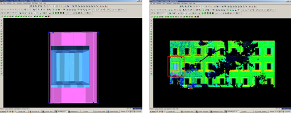
Figure 15 – (Left) Complex feature is grouped and copied (Right) Feature is pasted into the working ModelSpace – note that the feature inserts into the correct position based on the original scan data
[/wptabcontent]
[wptabtitle] DEFINE A “COOKIE CUTTER”[/wptabtitle]
[wptabcontent]
5. If the repeating feature requires a repeating opening, draw a polyline on top of the inserted group to define the opening (this polyline will be used as a “cookie cutter” to make subsequent openings in the wall surface; polyline opening should be slightly smaller than the feature to be inserted -> Place cookie cutter polyline on its own layer
6. Use polyline to create opening in primary (wall) patch (follow steps for “Creating Repeating, Identical Openings“) -> this opening now reveals the grouped window within the primary wall surface

Figure 16 – The large magenta rectangle highlights the entire group; the yellow polyline (representing the “cookie cutter” used to create openings in the primary surface) is slightly smaller than the group

Figure 17 – Opening has been made and the grouped window is revealed – note the yellow polyline “cookie cutter” and the group can be copied and repeated on the primary wall patch[/wptabcontent]
7. Select the Window Group and the “cookie cutter” polyline -> Copy to the next location; there are several methods for placing the repeating feature; two possibilities are outlined below, however different options can be mixed/matched:
7A. Copying and Locating by Pick Points > Multi-select 1st) Group/window 2nd) cookie cutter polyline 3rd) Point representing location where copied object is to be placed -> Create Object -> Copy
7B. Copy dialogue box appears and points that have been chosen are numbered -> Direction of Move, click on blue arrow -> Point to point, define points to use for direction of move and ok -> Distance of move, click on blue arrow -> Point to point, define points to use for distance and ok -> At main dialogue, confirm objects are correctly identified in the “Apply To” pull-down menu -> Copy
Note: If pick points do not show up correctly when copy dialogue box appears, you can re-define pick points while copy command is active; simply multi-select new pick points before defining direction and distance

Figure 18 – Window Group and Polyline are copied with Cyclone’s green arrow showing direction of copy – note that in this case, both the direction and the distance of the copy are from Point 7 to Point 8
[wptabtitle] MULTIPLE COPIES BY DISTANCE AND AXIS[/wptabtitle] [wptabcontent]
7C. Multiple Copies by Distance and Axis > Multi-select points representing 1st) the starting location of the object to be copied 2nd) the offset distance the object will be copied to -> Tools -> Measure -> Distance -> Point to Point -> Annotation showing distance appears
7D. Continue multi-select command -> Select Object(s) to be copied -> Create Object -> Copy -> Direction of Move -> Choose Axis and ok (arrow appears showing which axis will be used for the copy – note that the direction copy is placed along axis is defined by a positive or negative number in the distance)
7E. Distance of move -> Custom -> Enter amount derived with measure command and ok (a negative or positive possible determines the direction on axis) >Main Copy Dialogue box -> Enter Number of copies – note that copies will be offset from each succeeding copy, NOT from the original start location -> Confirm command applied to objects correctly -> Copy
NOTE: Any error will increase as distance increases; therefore it’s important that you examine each copy for accuracy and manually adjust as needed, especially those copies at the greatest distance from the original

Figure 19 – Multiple copies (highlighted in magenta) are offset from one another; openings can be seen in the green, point cloud data – note that as distance increases from the original left group, the error between the proposed opening/group and the accurate opening in the point data also increases and must be adjusted[/wptabcontent]
[wptabtitle] REFINING THE PLACEMENT OF REPEATING FEATURES[/wptabtitle]
[wptabcontent]8. Refining the placement of Repeating Features – as noted, small errors in distance increase with repetition/distance. Using the point cloud and the constraints in Cyclone are essential to accurately placing and locating features. In this example, the primary patch (the wall) is located along the x-axis. As succeeding windows become mis-aligned with the actual point cloud openings, windows are adjusted individually to rectify the model with the point data.
For distance moved, specific points are used – in this case the window sill protruded creating a discernible corner to match with the model’s sill corner.
Direction moved is restricted to the x-axis – this ensures that (1) the succeeding windows stay horizontally aligned with the original and (2) all windows stay along the same plane (the main wall where original window was placed).
Note: Surfaces are very rarely perfectly orthogonal and flat; rather they usually have fluctuations and they deviate from perfect angles. As such, when comparing a flat surface that has been modeled to the point cloud data, points should appear dispersed on both sides of the plane/patch; all points should not be completely located on one side or the other as this indicates the plane is not directly referencing the points.

Figure 20 – (Left) A window is misaligned with the point cloud data; zooming in allows the user to use the points very precisely; movement by picking points allows accurate placement of specific features, such as corners, while moving by a standard axis allows orthogonal alignment with other objects, planes, and references (Right) Window is rectified with the x-axis and specific points on the window sill. Note that the visibility of the primary patch (the main wall) has been turned off for clarity of other layers.[/wptabcontent]
[wptabtitle] MISSING DATA AND COMBINING RESOURCES[/wptabtitle]
[wptabcontent]9. Missing data and combining resources – While point cloud data and axes help accurately place most features, in some cases data is simply not present. In these cases, utilizing other resources is essential to creating a complete model that is as accurate as possible. In this example, a tree left a large shadow in the wall and placing windows within this shadow becomes difficult with point cloud data alone.
Utilizing measurements – finding the average distance between other windows and placing the windows in shadow at this offset helps place the windows fairly accurately.
Comparing the model with the photographic data collected during scanning further assists in accuracy.
[/wptabcontent]
[wptabtitle] CREATE OPENINGS IN PRIMARY WALL PATCH[/wptabtitle] [wptabcontent]10. Once each group has been evaluated and placed accurately -> use the cookie cutter polyline to create openings in the primary wall patch as shown in Step 5 of this section -> Erase or hide the polylines as needed once used (erase if merging back into the original ModelSpace and lines are no longer needed; hidden if copying into original ModelSpace and you want to maintain reference objects in the working ModelSpace).

Figure 21 – (Left) Windows, in dark blue, have been individually analyzed and adjusted for accuracy with the point cloud, in green (Right) Openings have been made in the primary wall patch, in light blue; the dark blue window groups are revealed.
[/wptabcontent] [/wptabs]