The following instructions explain set up and operate the Trimble 5700 GPS Receiver for use in a RTK application.
Hint: You can click on any image to see a larger version.
[wptabs style=”wpui-alma” mode=”vertical”] [wptabtitle] HARDWARE [/wptabtitle]
[wptabcontent]
Required hardware:
1. Trimble 5700 receiver w/ CompactFlash card
2. Trimble Lithium Ion batteries (2) or external battery back
3. Zephyr or Zephyr Geodetic antenna, w/ antenna cable and brass tripod adapter
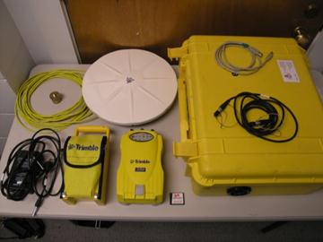
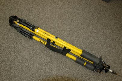
4. Fixed-height tripod
[/wptabcontent]
[wptabtitle]SET UP: I [/wptabtitle] [wptabcontent]
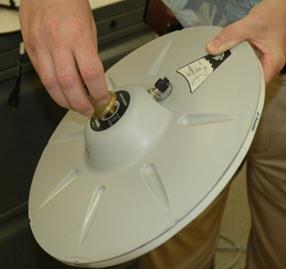
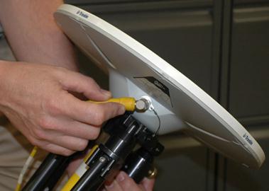
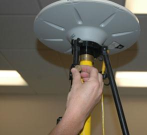
1. Remove the Zephyr or Zephyr Geodetic antenna from the case, and screw in the brass tripod adapter.
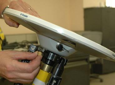
2. Stand the fixed-height tripod on its center tip, loosen the brass thumbscrew in the side of the top mounting plate, insert the brass adapter on the Zephyr antenna into the mounting hole, and then tighten the thumbscrew.
[/wptabcontent]
[wptabtitle]SET UP: II [/wptabtitle] [wptabcontent]
3. Remove the cover from the cable socket on the antenna, and then screw the angled connector on the yellow antenna cable on to socket. Be careful to keep the cable untangled; you can safely assume that most of these specialized cables cost well over $100!
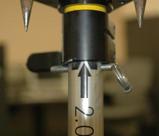
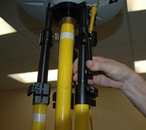
4. At the base of the tripod, flip the lever to release the center leg, and then extend it fully to the 2-meter mark. There is metal pin attached by a wire to the base of the tripod. Insert the pin through the holes in the rod at the 2-meter mark, then put the weight of the tripod on to the center pole so that the pin is pushed firmly against the clamp body.
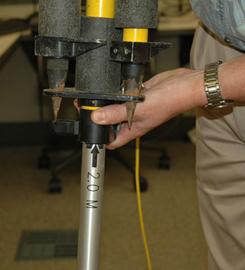
5. Now flip the lever to lock the clamp.
[/wptabcontent]
[wptabtitle]SET UP: III [/wptabtitle] [wptabcontent]
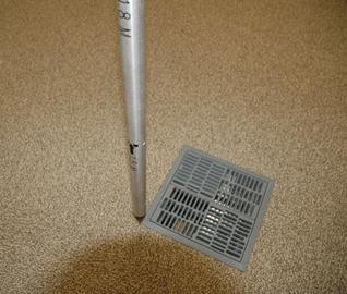
6. Carefully place the tip of the center pole at the exact spot on the ground that you wish to survey (in this sample photo, it is the corner of a floor vent).
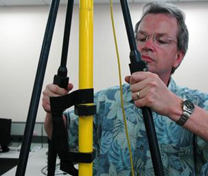
7. Two of the side legs have squeeze clamps at their upper end.
To release them from the tripod base, squeeze the clamp and lift the leg up so that the tip clears the base.
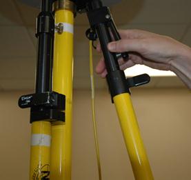
Angle the leg away from the tripod body and flip the lever to release the lower clamp on the leg. Extend the lower portion of the leg all the way, and then lock the clamp again.
[/wptabcontent]
[wptabtitle]SET UP: IV [/wptabtitle] [wptabcontent]
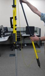
8. Finally, use the squeeze clamp to extend the leg all the way to the ground, forming a stable angle with the center pole. Repeat this operation with the second leg that also has a squeeze clamp.
9. The third leg is different; instead of a squeeze clamp, it uses a thumb screw to tighten the upper section. Loosen this thumbscrew, and then extend the leg and place its tip as you did on the other two legs. Be sure to leave the thumbscrew loose. At this time, if your are on soft ground, you should use your foot to push each of the three legs (not the center pole)into the ground.
[/wptabcontent]
[wptabtitle]SET UP: V [/wptabtitle] [wptabcontent]
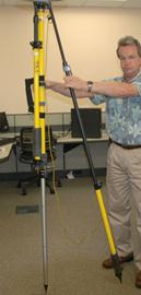
10. The tripod must be completely level to get an accurate measurement. Locate the bubble level mounted on the side of the tripod.
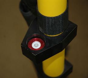
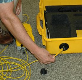
Place a hand on each of the squeeze clamps, squeeze them to release their lock, and very carefully push or pull to align the air bubble in the level within the inner marked circle. When you have the tripod level, release both of the squeeze clamps, and check your level again. If it is still level, lock the thumbscrew on the third leg, and you are finished with the tripod.
11. If the field case for the receiver you’re using has cable pass-through (a black, round plug in the side of the case), you can unscrew it and thread the antenna cable through the opening (this will let you put the receiver and batteries in the case with the lid shut). Regardless of which case you’re using, the next step is to remove the cap for the antenna connector on the 5700 receiver, and then connect the yellow antenna cable.
[/wptabcontent]
[wptabtitle]SET UP: VI [/wptabtitle] [wptabcontent]
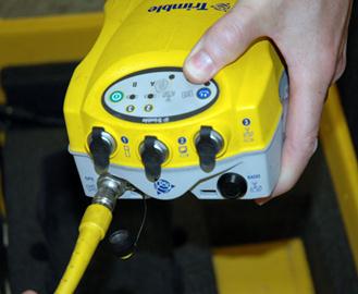
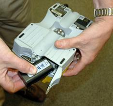
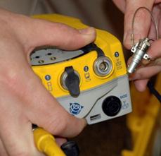
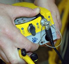
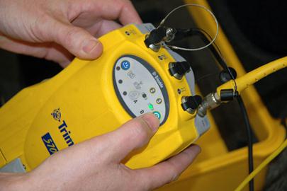
12. For power, there are two options. A pair of lithium-ion batteries can be inserted into the bottom of the 5700 receiver, or an external battery pack can be plugged into it. When plugging in the battery pack, be sure that the red dots align on the plug and connector. The battery pack can be plugged into either connector 2 or 3 on the receiver.
13. When disconnecting the battery pack, release the plug by pulling on the steel wire loop attached to it.
[/wptabcontent]
[wptabtitle] OPERATION: I[/wptabtitle] [wptabcontent]
1. Turn on the 5700 receiver by pressing the green power button. The unit will do a quick self-test, and will indicate healthy batteries by green lights for the A & B positions (if you only have one battery or battery pack connected, only one of the battery lights should illuminate).
[/wptabcontent][wptabtitle] OPERATION: II [/wptabtitle] [wptabcontent]
2. At this point in time, record the start time for this location on the GPS log form. Press the blue button to begin logging.
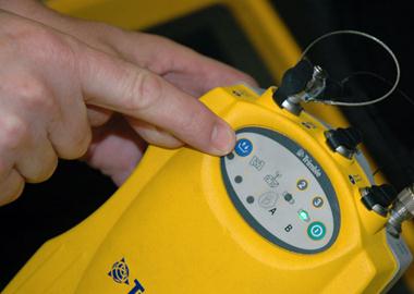
The red SV Tracking LED below the satellite icon indicates the status of satellite tracking:
- Slow flash – Tracking four or more satellites.
- Fast flash – Tracking three or fewer satellites.
- Off – Not tracking any satellites.
-
On – The receiver is in Monitor mode, and is checking for new firmware to install.
The yellow Logging/Memory LED below the blue Logging button indicates the status of data logging and memory usage:
- On – Data is being logged.
- Slow flash – Enough FastStatic data has been logged. Alternatively, if the red SV Tracking LED is on solid at the same time, the receiver is in Monitor mode, and is checking for new firmware to install.
- Fast flash – Data is being logged but memory is low.
- Flash – The receiver is in Sleep mode, and will wake up five minutes before the scheduled start time of a timed application file.
- Off – Data is not being logged, or the CompactFlash card is full.
[/wptabcontent]
[wptabtitle] OPERATION: III [/wptabtitle] [wptabcontent]
3. Take a clear photo of the tripod, making sure the actual survey point is very clear. Record the photo number on the GPS log form. Record the direction you were facing when you took the photo. Enter a clear description of the location, so that it can be easily located again.
4. For a FastStatic (also called “RapidStatic”) position, you will run the receiver for 20 minutes. At the end of this time, you should see both the Logging (yellow) LED and the SV Tracking (red) LED doing a slow flash. If the receiver shows to have successfully logged a FastStatic point by this behavior, press the blue Logging button for 2 seconds to stop logging, and then press the green Power button for 2 seconds to turn off the receiver. If the Logging LED is still “On” (not flashing), check that the SV Tracking LED is in slow flash mode; if it is in fast flash mode, then it is not tracking enough satellites to record adequate data. The receiver can be left running for an extended time, if necessary, until it indicates that enough FastStatic data has been logged.
5. Record the End Time for this location on the GPS log form.
[/wptabcontent]
[wptabtitle] DIS-ASSEMBLY[/wptabtitle] [wptabcontent]
Dis-assembly is the reverse of Setup. A few things to keep in mind:
Coil antenna cables in large loops so that they have no kinks or bends in them.
Be very careful with tripod points – they really can hurt people!
Make sure that the legs are properly locked after you’ve folded up the tripod.
When returning CAST equipment, it must be completely clean. Dust, dirt, grass, etc., are unacceptable – clean it up!
[/wptabcontent]
[/wptabs]