In this series, columns in a deteriorating colonnade will be modeled by several methods.
Hint: You can click on any image to see a larger version.
[wptabs style=”wpui-alma” mode=”vertical”]
[wptabtitle] IMPORTANT NOTE ON OBJECTS IN ACAD[/wptabtitle]
[wptabcontent]IMPORTANT NOTE ON OBJECTS IN ACAD: When using the following methods (EXTRUDE, SWEEPT LOFT, REVOLVE) you can create solids or surfaces. Whether the object is solid or surface is determined by 2 things:
(1) Whether the polyline is open or closed: Open polygons and curves always create surfaces but closed polylines and curves can create either.
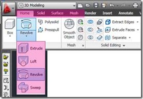
(2) Which tab is active at the top of the ACAD workspace (See Figure 1) – If the Solid tab is active, a solid is created; if the Surface tab is active, a surface object is created; if the Home tab is active, by default, a solid is created from closed polylines (this default can be changed once a command is active by entering ‘M’ for Mode at the prompt) – Solids seem to translate into the COE format and import into Cyclone much better than surfaces, which sometimes will not show up in Cyclone at all in the COE format.
Figure 1 – Main ACAD toolbar with modeling tabs highlighted in Magenta; EXTRUDE, LOFT, REVOLVE, AND SWEEP exist on each of the modeling tabs. Which tab is active and whether the polyline is open or closed determines what type of object is created.[/wptabcontent]
[wptabtitle] SET UP THE ACAD MODEL SPACE[/wptabtitle]
[wptabcontent]I. Set up the ACAD Model Space
1. Configure/Open the Cyclone MS and set up the ACAD model space (See the GMV’s “Leica CloudWorx 4.2 and AutoCAD 2012 – Digitizing a Point Cloud in 2D” for more information)
2. Create Layers for each of the 3 slices and the final column object, making the bottom slice’s layer active
3. Adjust the object geometry association variable in CAD -> command line: DELOBJ > adjust to value zero
(NOTE: This number determines whether the original geometry used to create a 3D object – in this case polylines – are retained or deleted when the object is created. This value can range from ‘0’ through ‘-3’, with ‘0’ retaining all geometry and with ‘-3’ deleting all defining geometry. Retaining geometry is recommended for analysis and any possible back-tracking. Search “DELOBJ” in ACAD help for more information)
[/wptabcontent]
[wptabtitle] SETUP ACAD MODEL SPACE – CONT.[/wptabtitle]
[wptabcontent]
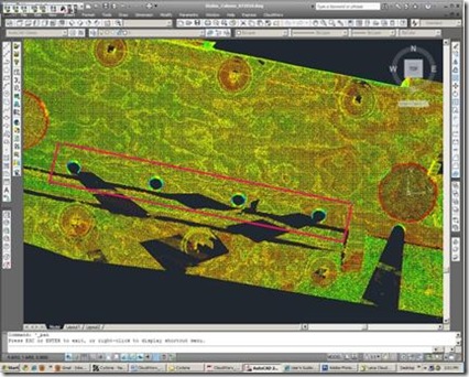
4. Hide Regions to isolate first feature to be modeled, in this case, the colonnade.
Figure 2 Top view of colonnade – roof and other un-needed data has been hidden with Hide Regions; colonnade (highlighted in the magenta rectangle) is easily evaluated for complete/intact features[/wptabcontent]
[wptabtitle] EXAMPLE[/wptabtitle]
[wptabcontent]Method 1: Slicing Cross Sections and Lofting – Point Clouds may be sliced to view specific sections or profiles to model; these slices are made across the x, y, or z axis based on the current UCS. Slicing large areas is useful when looking to see which features are the most intact/complete across a site. Slicing small areas allows for precise drawing/modeling. In this method, a column will be sliced and the section’s profile (ie: cross sections) will be traced and lofted into solid or surface objects.
In the first example, the column is sliced 3 times on the y-axis. Tracing the slices creates 3 polylines representing the section cuts from the bottom, middle, and top sections of the columns -> These cross sections will then be lofted to one another, forming the modeled column object.[/wptabcontent]
[wptabtitle] USE THE CLOUDWORX SLICE TOOLBAR[/wptabtitle]
[wptabcontent]II. Use the CloudWorx Slice Toolbar ![]() to slice the point cloud along the y-axis as the first section cut at the bottom of the column. Slices can be made in several ways. NOTE: a slice must be named in the Cutplane Manager (main Cloudworx toolbar) in order to be saved; if unnamed, it will be deleted once it is deactivated!!!
to slice the point cloud along the y-axis as the first section cut at the bottom of the column. Slices can be made in several ways. NOTE: a slice must be named in the Cutplane Manager (main Cloudworx toolbar) in order to be saved; if unnamed, it will be deleted once it is deactivated!!!
1. Clip Point to Slice -> uses two parallel planes to define the slice; only those points between the two planes are shown > Command line: CWSLICE or Cloudworx > Clip Point Cloud > Slice > Define Axis > LC in viewport to place 1st and 2nd clipping planes. NOTE: Current Slice can be moved one step (equal to width of the slice) forward (CWSLICEF) or backward (CWSLICEB) along its axis
[/wptabcontent]
[wptabtitle] CLIP POINTS TO SECTION[/wptabtitle]
[wptabcontent]
2. Clip Points to Section > uses single plane with only those points on one side of the plane visible > Command line: CWSECTION or Cloudworx > Clip Point Cloud> Section View > LC in viewport to define axis and direction (positive or negative)
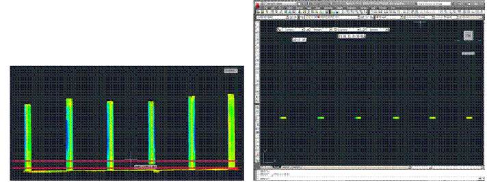
Figure 3 – (Left) Hide Regions command has isolated colonn cut; (Right) Sliced colonnade – note the points are not deleted, simply hidden ade – Clip-to-Slice command (slices shown by magenta lines) creates the first section[/wptabcontent]
[wptabtitle] TRACE AND SNAP TO POINT CLOUD[/wptabtitle]
[wptabcontent]
3. Trace first section cut, snapping directly to point cloud > Top View > Make correct layer current > Zoom in to view points comfortably and refresh point cloud to confirm all points visible ![]() (do this periodically, especially when zooming in/out) >Command Line: PL or POLYLINE to trace the profile/outline of the bottom slice of the column
(do this periodically, especially when zooming in/out) >Command Line: PL or POLYLINE to trace the profile/outline of the bottom slice of the column
REMEMBER: (1) Enable OSNAP “NODE” to snap to points (2) At command line: type “U” during active polyline command to undo vertices/go back without ending the command (3) At command line: PEDIT allows polyline(s) to be edited, joined, etc. (4) See ACAD Help: Drawing and Editing Polylines for more information
3A. Repeat Steps to create the polylines for the remaining section cuts (note you may create more or less slices as desired – a higher number of slices and/or increased complexity results in a more accurate tracing but also requires a higher and more difficult set of calculations to loft/join the separate sections; when too complex, the lofting command may fail to calculate the final object as desired) > Confirm each section is made of only one polyline (use PEDIT -> JOIN and PEDIT -> CLOSE to join and close multiple polylines)
3B. Once all section cuts are traced, hide the visibility of the point cloud ![]() -> make the column object layer current
-> make the column object layer current
[/wptabcontent]
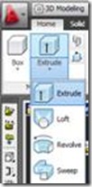
[wptabtitle] 3D MODELING MAIN TOOLBAR[/wptabtitle] [wptabcontent]III. 3D Modeling main toolbar > EXTRUDE tab pulls down to LOFT (see figure 4) or at command line: LOFT > Select cross sections in the order they are to be lofted to one another (here from bottom to top) > ENTER after selection > ENTER a 2nd time to accept “Cross Sections Only”
Figure 4 Extrude icon pulls down to reveal Loft and Revolve Icons in the 3D Modeling Workspace or enter LOFT at command line[/wptabcontent]
[wptabtitle] RETURN TO ORIGINAL COORDINATES AND EXPORT[/wptabtitle] [wptabcontent]IV. Return to Original Coordinates and export > If you have altered the Coordinate System, return it to the World Coordinate System that matches the original scan world coordinates (See the section: ‘Setting up a Model Space in AutoCAD: Using User-defined coordinate systems’ and Figure 4 for more information) > Modeled object can now be edited or exported as desired > Select objects > File > Export[/wptabcontent]
[wptabtitle] TIPS FOR LOFTING[/wptabtitle] [wptabcontent]TIPS for lofting: Attempting to loft more than 2 complex cross sections, such as highly detailed tracing, may freeze the program or take large amounts of time. If this happens, try lofting 2 polylines at a time to create separate objects and then grouping or converting these separate objects into a single surface or solid object as needed. Retaining the original geometry (ie: the polylines through DELOBJ) and using layers is essential to dividing the lofting command into manageable pieces; to join multiple objects -> NOTE: although multiple objects can be joined together into a single object with the UNION command, objects that have been united do not seem to translate into COE files well; if you have used the UNION command and find importing the COE file into Cyclone is slow or unsuccessful, try the original objects, pre-UNION (this is another case in which retaining your original geometry is very helpful).
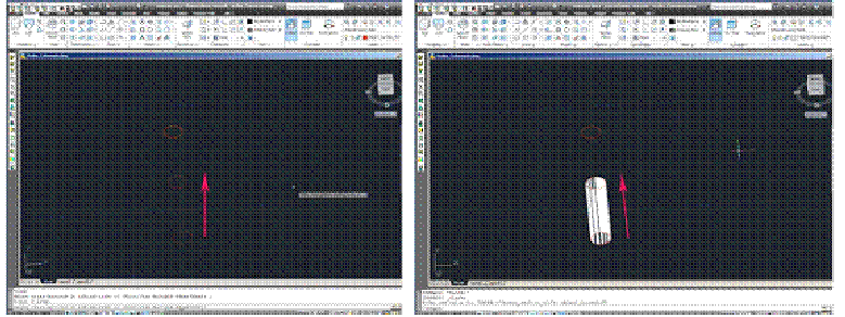
Figure 5 (Left) Each section cut has been traced as one polyline and the point cloud is hidden; 1st the bottom polyline and 2nd, the middle polyline are selected for lofting (the magenta arrow highlights the order of selection and lofting direction) (Right) 2 polylines create the first lofted object (ie: the bottom of the column)[/wptabcontent]
[wptabtitle] EXAMPLES OF LOFTING[/wptabtitle] [wptabcontent]
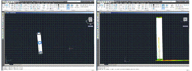
Figure 6 (Left) The column has been completely lofted into 2 objects (in white) and the original polyline geometry is still present and visible (blue and gray circles) – (Right) UNION has combined the 2 pieces of the column and the point cloud’s visibility is turned on for comparison[/wptabcontent]
[/wptabs]
