Match Photo Photography
Things to remember:
- Photos need to be taken at 45 degree angles of the corners of the structure to be modeled.
- Measure a section of the object to help with scaling.
- Do not crop photos, resize or warp.
- Barrel distortion can be used to correct straight lines that are bent away from the center of the image.
- Avoid images that have been stitched, such as panoramas.
- If possible try to avoid photos with excessive foreground features. These will make the modeling process difficult.
- Telephoto lens photos or images with only one vanishing point viewable are not recommended either.
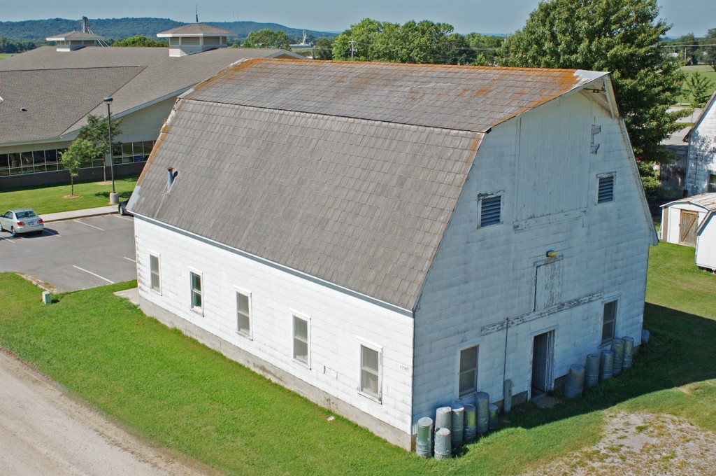
This image is taken from a boom lift, but conveys the 45 degree corner photo shot.
Model Creation using Match Photo
- Take pictures of each corner and side of the object, making sure to have overlap between images. If necessary, multiple images might need to be taken of a side to capture the whole area.

- Go to Camera > Match New Photo. In the Select background image file dialog box navigate to the first photo (this can be any corner shot) in your series of photos of your object and select it.
- Click Open, and the photo will be placed in the main drawing area in a scene specific to Match Photo. This is where you will calibrate the scene to match the photo.

- Select the origin axes and place it at a location where three axes might intersect. The origin will depend on the type of photo that you take. Photos can be taken indoors and corners of walls/ceilings/floors meet can be used for the origin. Of if you are looking down at the object, then using a top corner axes is more beneficial. The type of origin used will affect the grid style in the Match Photo tool, in the Match Photo dialog box select the grid style that matches the photo you are using. For the image below I have selected the middle grid style, denoting the origin axes at the top corner of the barn.

- Now the vanishing bars (the red and green dashed bars) need to be place to determine the vanishing point of the image. Select the end bar grips (
 )on each bar and place the bar on a line that represents a parallel line to each red and green axis line. Axis bars should be placed along the longest feature available in the photo. Zoom in to place each bar as accurately as possible.
- The work area needs to be scaled, so adjust the grid spacing to a number that can be matched to a feature with a known size in the photo. Select the blue axis and adjust up or down to match the grid to the feature with the known size. In the image below the grid spacing is set to 8 inches and the grid is scaled to match the barn siding which is 8 inches wide.

- Select Done in the Match Photo dialog box and begin drawing with the pencil tool. Always start at the origin and trace one side of the object. Do not rotate the scene, if you do, then returning to the Match Photo scene is done by simply clicking the Scene Tab at the top of the drawing window. Below is a traced side with the image projected. To project the image on to a surface, simply right click on a surface and select Project Photo.

- Using the Push/Pull tool easily starts the modeling process.


Special Items to Note:
- Due to a natural curvature in photographs caused by lenses, it’s impossible to match the perspective perfectly. To best combat the natural curvature in a photo, arrange your vanishing bars so that they are as long as possible. This arrangement creates a more accurate average of the perspective.
- Matching a cropped photo isn’t supported.
- Remember to model portions of the geometry not seen in the picture.