This workflow will show you how set up the Breuckmann Tripod and SmartScan HE for calibration prior to beginning your scanning project. Hint: You can click on any image to see a larger version.
[wptabs style=”wpui-alma” mode=”vertical”] [wptabtitle] TRIPOD LEGS SETUP[/wptabtitle]
[wptabcontent]
Start with the tripod in the closed position (all three legs together) and check that the legs are the same length, adjusting them if necessary.

Fig. 1: The brackets at the bottom and center of the tripod legs should be at the same level when the legs are closed, and all the feet should touch the floor at the same time.
Open the tripod legs by loosening the wingnut on the central pole of the tripod and sliding the legs outward. Create a wide triangular base with the tripod legs and tighten the wingnut.[/wptabcontent]
[wptabtitle]PLACE TRIPOD NEXT TO TABLE[/wptabtitle]
[wptabcontent]Place the tripod so that two adjacent legs are flush and parallel with the edge of the table or desk on which you have placed (or will place) the calibration chart.
Fig.2: Tripod feet are level and flush with the base of the desk

Fig.3: The lowest bubble level
If you are uncertain about which leg to adjust first, imagine drawing a line down the middle of each leg of the tripod extending through the bubble level. The line that passes closest to the center of the bubble is the leg you should adjust first. In this illustration where A, B and C mark the positions of the legs you should begin by adjusting leg C. To make the bubble move toward the center, level circle, leg C should be lengthened.
Fig.4: To move the bubble toward you parallel to any leg of the tripod, lengthen that leg. To move the bubble away from you, shorten that leg.
Continue adjusting the length of the legs following this logic until the tripod base is level.
[/wptabcontent]
[wptabtitle] ADJUST TRIPOD HEIGHT[/wptabtitle]
[wptabcontent]
5. Set the height of the tripod head so that it is roughly level with the center of the calibration chart by flipping out and then turning the handle, as shown below.
Fig.5: The central pole height is adjusted by turning this handle.
[/wptabcontent]
[wptabtitle] LEVELING TRIPOD[/wptabtitle]
[wptabcontent]6. Next, you want to adjust the tripod so that the second lowest level bubble is also within its level circle. This step is a little fiddly. The second level bubble essentially accounts for any deviations from level between the central pole, the bracket which attaches it to the tripod legs, and the tripod head. The goal is for the central pole to be just that – centered in the middle of the tripod base. Begin by checking that the tripod head is seated flat on the central pole. Loosen the two wingnuts that lock the position of the central pole. Shift the position of the central pole until the level bubble is within the circle and tighten the wingnuts. Be sure to check that this bubble is still indicating the tripod head is level after you attach the scanner to the tripod!
Fig.6: The tripod head.[/wptabcontent]
[wptabtitle] LEVEL TRIPOD 2- LOWEST ADJUSTMENT KNOB[/wptabtitle]
[wptabcontent]7. Use the lowest adjustment knob to align the front edge of the scanner attachment plate parallel to the edge of the desk or table. On the CAST tripod, this should be approximately at the 30° mark on the bottom dial.
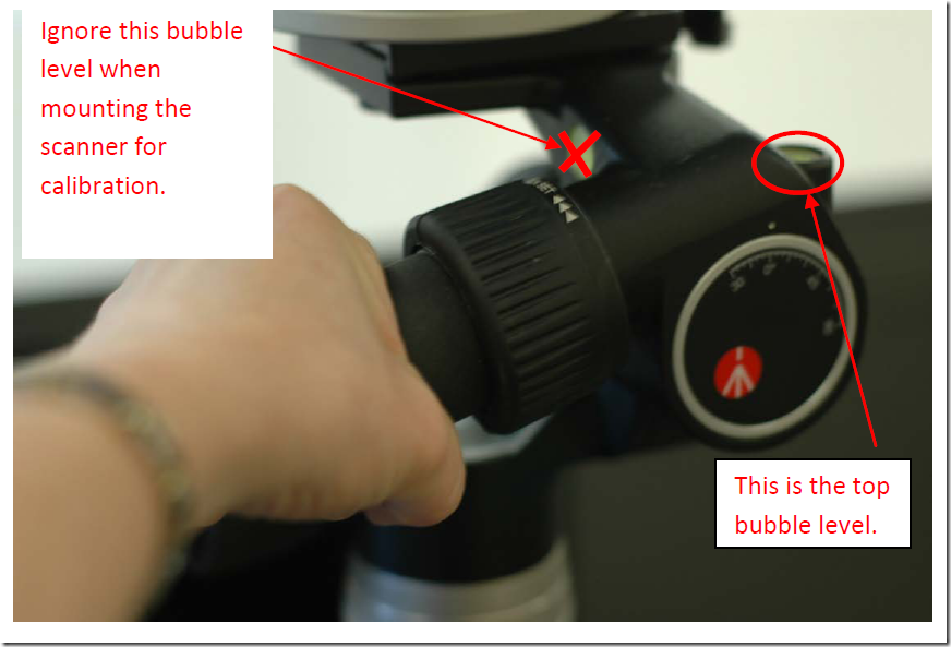
8. Finally, adjust the tripod head so that the top bubble is centered in the inner circle of the bubble level. The highest adjustment knob moves the scanner attachment plate along its long axis, the second highest adjustment knob moves the scanner attachment plate along its short axis.
Fig. 7: Tripod head adjustment guide.
Fig. 8: The top bubble level.
[/wptabcontent]
[wptabtitle] LEVEL TRIPOD 3- SIDE DIALS[/wptabtitle]
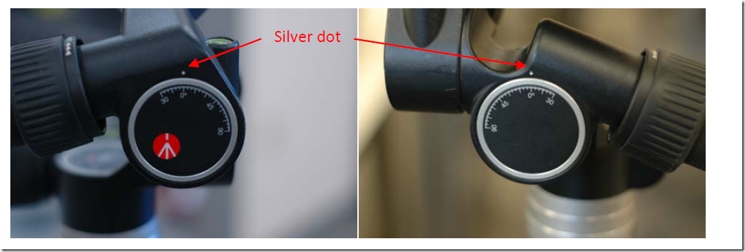
[wptabcontent]In addition to the top level bubble, you can use the two side dials as guides for setting the level of the tripod head. On flat ground both these dials should read approximately 0°. There is a small silver dot above each dial marking the 0° position.
Fig.9: Side dials on the tripod head.[/wptabcontent]
[wptabtitle] COARSE ADJUSTMENTS[/wptabtitle]
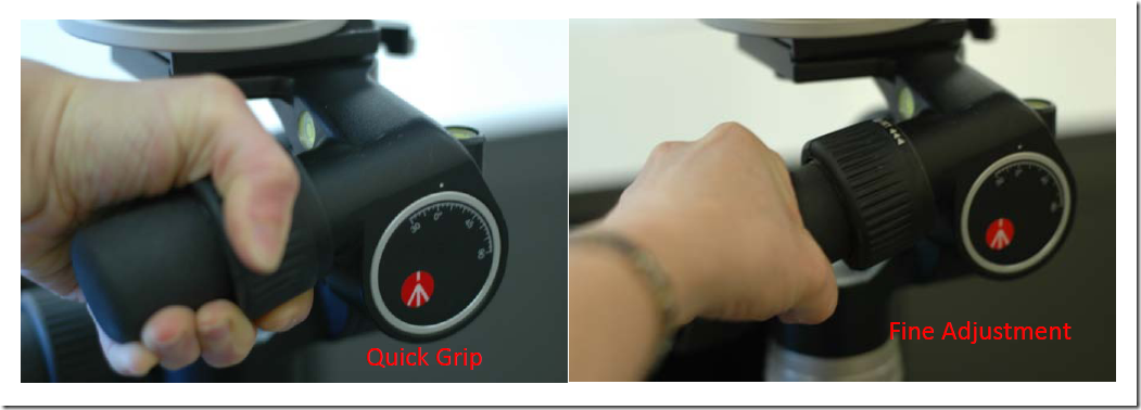
[wptabcontent](left) Quick, coarse adjustments are made by twisting the ‘quick grip’ and then pivoting the tripod head. Be careful using the ‘quick grip’ if the scanner is already mounted on the tripod head, as the uneven weight of the scanner can cause it to pivot faster than you might expect. (right) Fine adjustments are made by twisting the knob below the ‘quick grip’.
Fig.10: Quick grip and fine adjustment positions on the adjustment handles of the tripod head.[/wptabcontent]
[wptabtitle] FINAL CHECK[/wptabtitle]
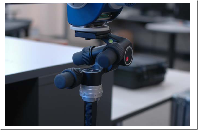
[wptabcontent]9. After you have leveled the tripod, attach the scanner and check and adjust the level if needed. At this point you should only need to make fine adjustments.
Fig. 11: The scanner mounted on the level tripod.[/wptabcontent]
[wptabtitle]SCANNER SHEET IN SCANNER CASE[/wptabtitle]
[wptabcontent]
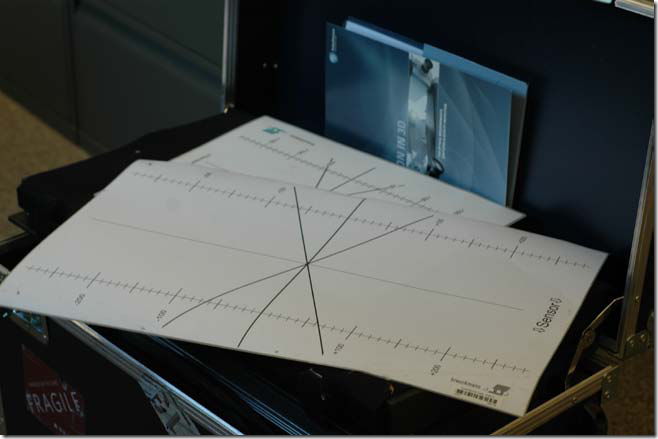
10. Once the scanner is positioned, put the chart placement guide on the table. Position the guide so its short edge is parallel to the edge of the table, and the side reading “SENSOR ” is pointed toward the scanner. Check the datasheet for the correct distance between the scanner and the center of the chart placement guide (approximately one meter). The datasheet and chart placement guide are stored in the lid of the scanner’s case.
Fig.12: The datasheet and chart placement guide in the scanner case.
[/wptabcontent]
[wptabtitle]CHART PLACEMENT[/wptabtitle]
[wptabcontent]
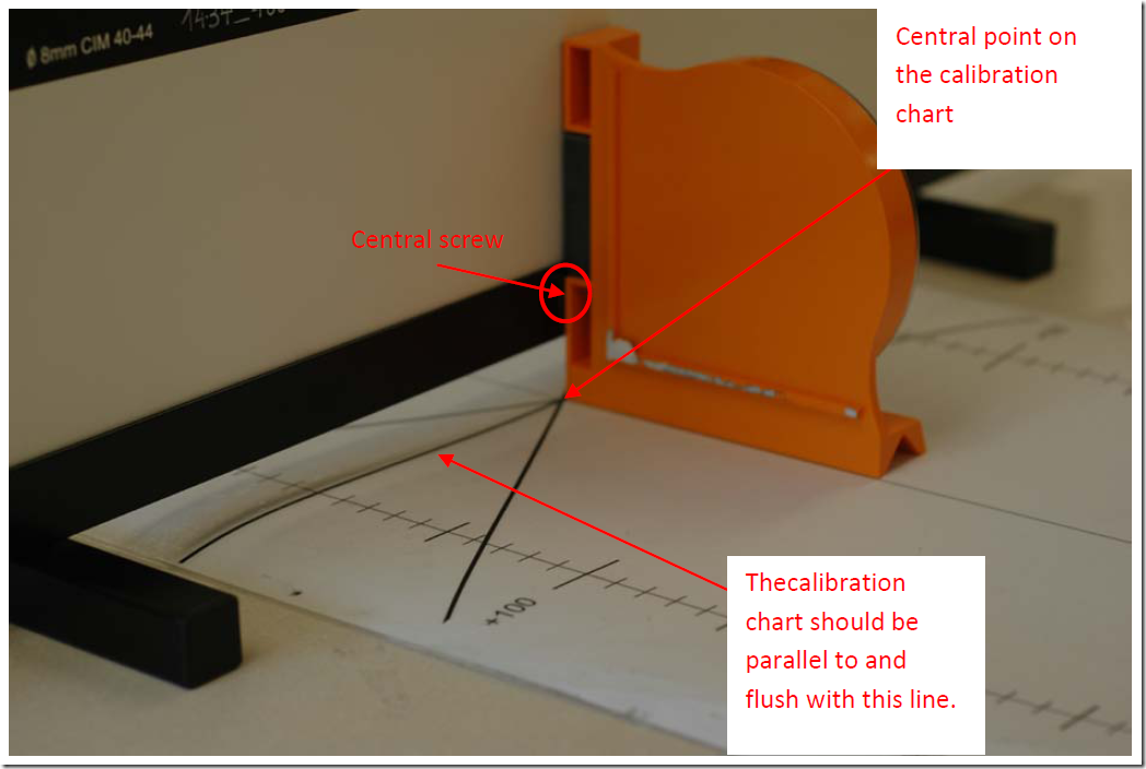
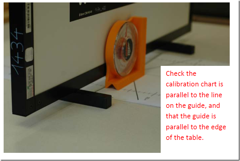
11. Place the Chart over the placement guide and center it. There is a screw in the center of the chart’s frame. This screw should be directly over the center line of the chart. You will probably want to use a
straight edge to ensure the calibration chart is parallel and flush with the center line on the placement guide.
Fig. 13: Aligning the calibration chart to the chart placement guide.
When everything is aligned, tape the chart placement guide to the table so it won’t move as you shift the calibration chart.
12. Alignment and leveling is complete!
13. You may now proceed with the calibration. (You may make some further fine adjustments to the height of the scanner and position of the chart once you have activated the lasers and live screen in the calibration.)
[/wptabcontent]
[wptabtitle] CONTINUE TO…[/wptabtitle]
[wptabcontent]
Continue to Section XXXXXX
[/wptabcontent]
[/wptabs]


