This series will show you advanced modeling building modeling techniques using Leica’s Cyclone.
Hint: You can click on any image to see a larger version.
[wptabs style=”wpui-alma” mode=”vertical”]
[wptabtitle] COPY TO NEW MODELSPACE[/wptabtitle]
[wptabcontent]In addition to modeling individual building walls, you also have the ability to trace the footprint of a building and extrude it up.
I. First, copy/subset the building into its own working ModelSpace > Draw a fence around the building > RC > Copy to MS
II. Next, show the Active Reference Plane. Depending on what you were working on last, the reference plane will probably be in a different location. Because we are tracing along the base of the building, we can use the standard top down view as a basis for creating our footprint sketch.
1. View –> Standard Views -> Top.
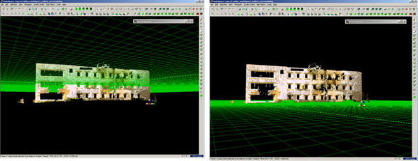
2. Select Tools –> Reference Plane –>Set to Viewpoint; this aligns the reference plane to the Top view. Note in Figure 1, the plane passes right through the middle of the building. In order to place the plane at the bottom of the building (so that our footprint sketch is placed along the building base), select a point at the very bottom of the building and then select Tools –> reference Plane –> Set plane origin at pick point. This translates the plane down to the building base.
Figure 1 (Left) Setting the Reference Plane to align with the Top-down Viewpoint (Right) Moving the Reference Plane down to the building base
[/wptabcontent]
[wptabtitle] SELECT VIEW AND TRACE THE BUILDING[/wptabtitle]
[wptabcontent]III. Select View –> Top DO NOT ROTATE THE VIEW (if necessary, choose View – View Lock – Rotate to constrain the view) > IMPORTANT:Change the View from Perspective to ORTHAGONAL (hot key ‘o’).
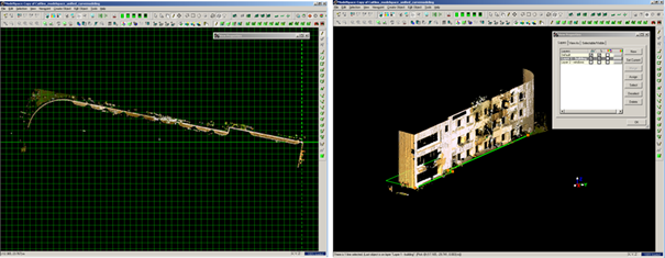
IV. Trace the building footprint using a series of polylines/curves (splines). Make sure you snap all of the handles together so that the curves create a closed object.
Figure 2 (Left) View constrained to top-down/orthogonal (Right) Series of curves drawn around the base of the building[/wptabcontent]
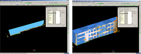
[wptabtitle] SELECT AND EXTRUDE[/wptabtitle] [wptabcontent]V. Multi-select all of the curves -> Create Object –> From Curves –> Patch. If necessary, add additional handles to patch and modify as necessary.
Figure 3: (Left) Patch created from series of curves representing the base of the building (Right) Patch extruded up to approximate shape of entire building
VI. Extrude the patch -> Multi pick 1st) the patch and then 2nd) a single point on the roof of the builidng -> Edit Object –> Extrude –> Extrude to Last Pick. The patch should then be extruded up to the roof height and all of the walls should be accurately modeled.[/wptabcontent]
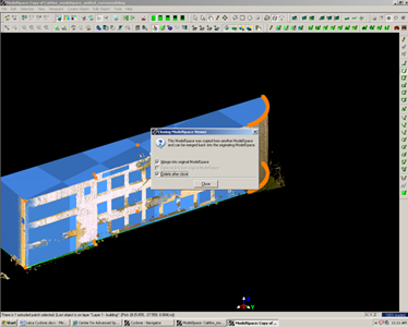
[wptabtitle] MERGE MODELSPACE INTO ORIGINAL[/wptabtitle] [wptabcontent]VII. Finally, close the ModelSpace and to merge the modeled results back into the original project > select Merge into Original ModelSpace and Delete after Close (if desired) > Option to merge appears once the close command is selected
Figure 4 Close ModelSpace and merge modeling results back into original ModelSpace
[/wptabcontent]
[wptabtitle]CONTINUE TO…[/wptabtitle]
[wptabcontent] Continue to Modeling Openings in Objects[/wptabcontent]
[/wptabs]


