This workflow will show you how to begin modeling in Leica’s Cyclone.
Hint: You can click on any image to see a larger version.
[wptabs style=”wpui-alma” mode=”vertical”] [wptabtitle] GETTING STARTED[/wptabtitle] [wptabcontent]
Getting Started
- Cyclone Navigator –> Project –> Model Space -> Open/Copy/Delete Model Spaces here
- Draw a fence to select the area to be modeled. The fence tools are located in the ‘Mode’ toolbar next to the navigation tools. Once the points are “fenced”, copy them into a new Working Model Space (Select –> Right Click –> Copy Fenced to new Model Space)
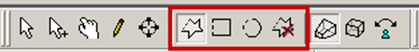 Figure 3: Fence Tools
3. Unify or Merge the clouds in the new MS (See Temporary Model Spaces Above)
[/wptabcontent]
[wptabtitle] MODELING A FLAT SURFACE: METHOD 1[/wptabtitle] [wptabcontent]
Modeling – Creating a patch to represent a wall or flat surface:
Method 1 – Fit to Cloud (More conservative):
- Draw a fence across flat surface using appropriate fence tool.
-
Once the fence has been drawn, RC, select Point Cloud SubSelection – Add Inside Fence.
- Next, make sure there are no points BEHIND the flat surface that accidentally got selected. If there are, draw another fence around them, RC – Point Cloud SubSelection – Remove Inside Fence (may have to repeat multipe times)Once you have the flat surface properly selected, select Create Object –> Fit to Cloud –> Patch.
 Figure 4: (Left) Selecting points in a dataset (Right) Rotating the dataset and removing the points that were erroneously selected behind or “through” the data
[/wptabcontent]
[wptabtitle] METHOD 2[/wptabtitle] [wptabcontent]Method 2 – Fit to Fenced:
- Draw a fence across flat surface using appropriate fence tool (making sure to not select any points behind the flat surface). RC –> Select Fit Fenced –> Patch.
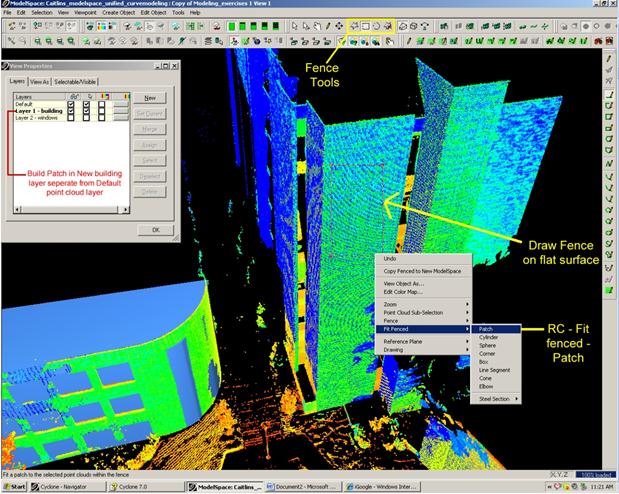 Figure 5: Process of drawing a fence on a flat surface then simply right clicking and selecting Fit Fenced – Patch
[/wptabcontent]
[wptabtitle] METHOD 3[/wptabtitle]
[wptabcontent]Method 3 – Region Grow (Relies on Cyclone and placed parameters to decide how patch forms)
- Select a point that is at the center of the area or surface to patch (Selection Tool -> Left Click); Note: the Region Grow command evaluates the points in a radius from the point selected
-
Create Object –> Region Grow –> Patch
- The Region Grow Dialogue Box allows the user to adjust the number of points that Cyclone uses to calculate the surface of the patch
- Region Thickness – thickness/depth of point cloud data used for region; lowering this number increases accuracy; be aware of changes in the depth of surface materials such as the mortar between bricks when adjusting this number.
- Maximum Gap to Span – maximum hole or shadow in cloud point data to “jump” and continue calculating the region
- Angle Tolerance – used for meshes only
- Region Size – the diameter radiating from the central pick point to calculate the region
 Figure 6: (Left) Region Grow with maximum region size – the white points represent the proposed patch. (Right) Reducing the region size so that fewer points are considered for the proposed patch – note the radial pattern with the first selected point at the center.
[/wptabcontent]
[wptabtitle] CONTINUE TO…[/wptabtitle]
[wptabcontent]Continue to Leica Cyclone 7.0: Modeling – Editing, Extending, and Extruding Patches[/wptabcontent]
[/wptabs]