This workflow will show you how to create basic geometries and trace topography in Leica’s Cyclone software.
Hint: You can click on any image to see a larger version.
[wptabs style=”wpui-alma” mode=”vertical”]
[wptabtitle] DEFINITIONS[/wptabtitle]
[wptabcontent]Definitions: Vector Objects are geometrical primitives, such as lines, curves, and polygons, that can be used to represent a surface or feature. These geometries can be 3D or 2D, depending on how they are created. These objects can be exported and used as two dimensional drawings (for site plans or printed documentation) or as three dimensional objects (in CAD or GIS software). Creating lines two dimensionally through tracing, is highly dependent on the user’s interpretation and basically comes down to visually
Definitions: Break lines are lines or polylines that sub-divide topography into reasonably sized sections; they represent the edges of a paved surface, a ridge, a channel, or any other topographic feature that the user wants to preserve. In vector drawings, break lines consist of lines, curves, and splines. In meshes, break lines become the edges that the triangles in the mesh conform to, defining and controlling the smoothness and continuity of the mesh. Whether creating a vector drawing or a mesh, tracing the break lines and other lines making up the site is one of the first steps.[/wptabcontent]
Workflow for Tracing Topography and Site Elements – 2D: Please see ‘Lecia Cyclone: Interface Basics’ and ‘Beginner’ and ‘Advanced Workflows for Building Modeling’ for an introduction and an overview of topics not covered here.
[wptabtitle] OPEN A REGISTERED UNIFIED MODEL SPACE[/wptabtitle]
[wptabcontent]I. Open a Registered Unified Model Space -> Create fence around ground plane –> Right Click –> Copy Fenced to new Model Space (NOTE: viewing from a standard side, front, or back view in orthographic mode assists in selection) -> Original MS may be closed
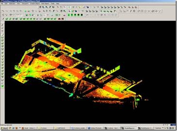
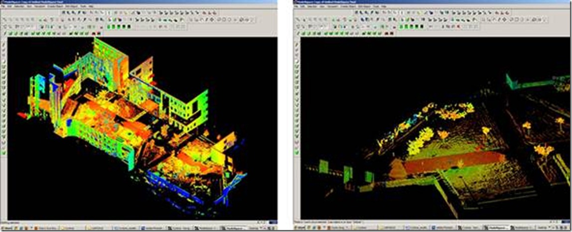
Figure 1 – (Left) Original registered scan world of plaza (Right) Point Cloud Sub-Selection (Select -> Right Click -> Point Cloud Sub-Selection) allows unneeded points, such as trees and vertical surfaces, to be deleted; Sub-selection allows the user to precisely choose and view points before deciding to delete[/wptabcontent]
[wptabtitle] SELECT AND DELETE UNNEEDED POINTS[/wptabtitle]
[wptabcontent]II. In the new Working MS -> -> Select and delete unneeded points: it’s best to eliminate as much vertical surface data as possible so that the ground plane to be modeled is isolated. While tracing, deleting unneeded data is primarily used to clarify details being traced; it becomes more important when meshing.

Figure 2 – The same plaza as Figure 1 now copied to a working MS and “cleaned” of unneeded vertical surfaces and vegetation leaving only the ground plane to be modeled
III. Identify break lines and level of detail -> Create a new layer for the break lines (Access Layer Manager by Shift + L) and make this layer current (Highlight layer & click ‘Set Current’) -> Review the area to be modeled and identify areas where the surface changes and/or where you want a clean break or difference between adjacent surfaces. We will create lines in these areas. Create layers for primary and secondary features as needed depending on the complexity of site.[/wptabcontent]
[wptabtitle] SHOW THE ACTIVE REFERENCE PLANE[/wptabtitle] [wptabcontent]IV. Show the Active Reference Plane. In Cyclone, when using 2D Drawing Mode, the Active Reference Plane plane becomes the location along which all drawn objects are located. For example, in Top View, which we will be using, all objects have their z-coordinates on this plan. It is comparable to the piece of paper upon which a site is drawn by conventional methods.
NOTE: Commands are based on the active reference plane. There is always a plane active whether it is visible or not. Planes can be activated and edited in the RP Manager (Tools > RP > Add/Edit)
NOTE: Creating and placing 3D polylines/curves with an accurate z-coordinate is covered in the document ‘Leica Cyclone – Creating a Mesh and Modeling Surface Topography 3D’.
[/wptabcontent]
[wptabtitle] SHOW THE ACTIVE REFERENCE PLANE 2[/wptabtitle]
[wptabcontent]V. In general, we will trace along the edges of features, either where a feature meets the ground plane or where the ground plane changes. -> To place Reference Plane:
A. Tools –> Reference Plane –>Set to Viewpoint; this aligns the reference plane to the Top view. If you notice in the next image, the plane passes right through the middle of the site.
B. Move the plane to the base of the site -> Select a point at the lowest significant point on the site -> Tools –> reference Plane –> Set plane origin at pick point. This translates the plane down to the site base.
[/wptabcontent]
[wptabtitle] SELECT TOP VIEW[/wptabtitle]
[wptabcontent]VI. Select Top View -> All tracing will be done in top view; it is important not to rotate the view, if necessary choose View –> View Lock –> Rotate
VII. Select Orthogonal View -> Hot key ‘O’ (hot key toggles between orthogonal and perspective
Figure 3 – (Left) Setting the Reference Plane to align with the Top-down Viewpoint (Right) Moving the Reference Plane down to the lowest point on the site[/wptabcontent]
[wptabtitle] TRACE SITE FEATURES W/ 2D DRAWING MODE[/wptabtitle]
[wptabcontent]
VIII. Use 2D Drawing Mode to trace site features -> Select a drawing tool -> ->Trace the feature of interest -> Accept/Create the drawing by either clicking the green check button at the top of the Drawing Toolbar or RC -> Create. The 2D sketch should turn bright green with orange handle at the intersections. Edit the line/sketch as needed (see editing some editing options in following steps).
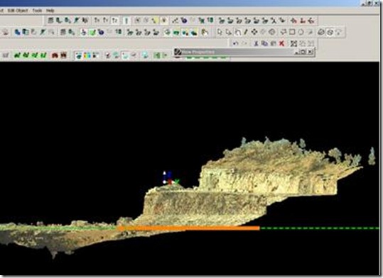
Figure 5 – A side view shows that the polylines representing the edges of the 2 stairs (in orange) are located at a single height/z-coordinate along the active reference plane (in green). [/wptabcontent]
[wptabtitle] TRACING TIPS[/wptabtitle]
[wptabcontent]Tips – Object Types: Lines and polylines are open objects (with a beginning and an end); polygons are closed objects (with an area and a perimeter); curves can be created through picking a variety of points. Polylines are usually the best tool for fairly straight features. In general, it is best to have one polyline than multiple individual lines representing a feature. Any feature that you ultimately plan to extrude or model 3-dimensionally should be a closed object.
Tips: Use the Modes Toolbar ![]() to navigate within the space while drawing mode is active; while drawing, LC the hand icon to pan and LC the pencil icon to return to the current line/arc. Also use the Modes Toolbar to toggle between orthogonal and perspective views.
to navigate within the space while drawing mode is active; while drawing, LC the hand icon to pan and LC the pencil icon to return to the current line/arc. Also use the Modes Toolbar to toggle between orthogonal and perspective views.
Tips – Accuracy: The level of detail/accuracy depend on many things including the ultimate needs, user interpretation, level of zoom and point width while drawing. It is recommended to choose and use a consistent method (same level of zoom, same point width) for similarly sized features to improve the chances of multiple users creating similar results in an area. With irregular features, often using a polyline with many vertices represents a curve more accurately than geometrically correct arcs.[/wptabcontent]
[wptabtitle] SNAP LINES AND POLYLINES TOGETHER[/wptabtitle]
[wptabcontent]IX. Snap ends of lines or polylines together -> Multi-pick two line (or polyline) segments to snap together -> With multi-pick, click and hold the handle of one of the lines -> Hold Shift while dragging the line toward the handle of the 2nd line until they snap together -> These lines are not joined, they remain separate entities
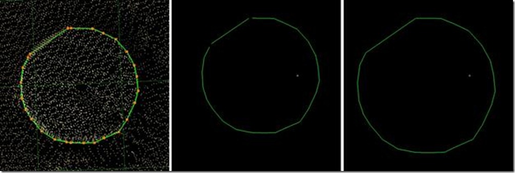
Figure 6 – (Left) The base of a column has been traced with a polyline and a line; (Middle) The point cloud’s visibility is turned off showing the two independent objects; (Right) The ends of the 2 objects have been snapped together but they remain as independent entities[/wptabcontent]
[wptabtitle] MERGE LINES OR POLYLINES TOGETHER[/wptabtitle]
[wptabcontent]X. Merge lines or polylines together -> With multi-pick mode, pick each of the lines to be merged -> Create Object -> Merge -> Multiple objects now become a single object -> Snapping the end handles together and merging creates closed objects.
NOTE: Only similar objects can be merged (i.e.: lines to lines, polylines to polylines); In some cases polylines disappear due to the order the polylines were selected; If the line disappears after merging, undo, and reverse the order the lines are selected
NOTE: Toggling the visibility of points and objects (Property Manager > Shift + L), and adjusting the visibility of the Reference Plane (Tools > RP > Add/Edit), can help clarify what you are drawing.
XI. Extend a line -> Pick line (with pick mode NOT multi-pick) -> Pick the end handle, hold and drag (line will extend in same 3D direction as original line) OR Pick the line, multi-pick a point in the point cloud that you want to extend the line to -> Edit Object -> Extend to last selection (the line will extend in the direction it was originally created)[/wptabcontent]
[wptabtitle] EXPORTING[/wptabtitle]
[wptabcontent]XII. Exporting: There are several options for exporting topographic features. The objects created through tracing can be exported or the point cloud itself can be exported.
A. Export the lines, polylines, arcs -> Use the properties manager (Shift + L) to turn off the visibility/selectability of the point cloud -> Select All -> File -> Export
- 2D DXF R12 Format – all objects export on a single 2-dimensional plane (in this case the active RP) – use this setting for 2D applications
- DXF R12 Format – 3D information is retained (in this case the z-coordinate for the lines) – use this setting if the objects have different z coordinates
- Objects may also be exported as ASCII or XML file types here
- Once exported, the .dxf file can be opened in CAD, imported into Sketchup, or converted for multiple software.
B. Newer versions of AutoCAD (2009 and beyond) support point clouds. If you do not have Cyclone but you do have CAD, use Cyclone to export the points and then trace/model in CAD software much as we have done in Cyclone. The main issue is file size; in general, point clouds must be broken into smaller pieces to allow them to be imported into CAD software. See the CAST workflow, ‘Reducing Point Clouds for Autodesk Applications’ for more details.
NOTE: In general, export .PTS file types with a maximum size of 4mb to import into CAD as of 2011
[/wptabcontent] [/wptabs]


