This workflow will show you how to import Optech data into IMAlign, part of Polyworks V11
Hint: You can click on any image to see a larger version.
As objects become more complex, using layers (Shift + L) becomes essential to organizing and controlling the model space.
[wptabs style=”wpui-alma” mode=”vertical”] [wptabtitle] IMAlign INTIAL SETUP[/wptabtitle] [wptabcontent]![clip_image002[4] clip_image002[4]](https://gmv.cast.uark.edu/wp-content/uploads/2011/10/clip_image0024.jpg)
Figure 1: Set IMAlign options as suggested below prior to importing any data
IMAlign is the Polyworks module that allows you to import and align scan data. When you first open IMAlign, it’s good to define a couple of parameters. Before you import any data, open IMAlign options and change the Digitizer from Generic Close Range to Optech ILRIS 3D and change the working units to meters. Also, turn off the Interactive Mode Wizard and the Unknown Units Wizard. Also, under the Alignment section change Subsampling from 1/4 to 1/1 and under the Images section set Max Angle to 85 (see illustration below under Section 4). Next, go to Tools – Save Configuration (to save the new settings).[/wptabcontent]
[wptabtitle] DISPLAY PARAMETERS[/wptabtitle] [wptabcontent]![clip_image004[4] clip_image004[4]](https://gmv.cast.uark.edu/wp-content/uploads/2011/10/clip_image0044.jpg)
Figure 2: The eye icon controls how objects are displayed in the scene
Object color Mode Point or Default
Default Static Display
Drawing Type: Smooth or Flat
Subsampling: 1/1
Default Dynamic Display (Recommended parameters bolded/italicized)
Drawing Type: Point
Subsampling: 1/16 or 1/64[/wptabcontent]
[wptabtitle] IMPORTING OPTECH DATA[/wptabtitle] [wptabcontent]
Importing Optech Data (.pf format)
1. Go to File – Import Images – 3D Digitized Data Sets. Under Spherical Grids, choose Optech PIF. Next, navigate to the file, and select Open. Typically, you will not subsample the data set (choose 1/1), however if file size and/or memory become an issue, the only place to subsample or decimate a data set in IMAlign is upon import.
The following is a basic description of the import parameters and additional guidance for modifying parameters.
Note: Always hit the Reset button before adjusting any import parameters. Previous import settings are retained.
When Optech data is imported into IMAlign, the data is automatically “gridded” or meshed. For spherical datasets like Optech data, IMAlign does this by subdividing the data by angle and range and then assigning a plane to each data section and then meshing that individual section. Therefore subdividing Optech data by both angle and range (or distance) is recommended. The smaller the angle, the more subscans created. A Subdivision Angle of 20 is generally recommended, however you might want to lower this value to 10 if there is a lot of ground/floor data in a scan.
Figure 3: Interface for importing Optech data into IMAlign[/wptabcontent]
[wptabtitle] INTERPOLATION OPTIONS – FOCUS[/wptabtitle] [wptabcontent]Interpolation Options
Focus Distance: The minimum distance, or the point at which data is first recorded. – Typically leave as is.
Step at Focus: The data resolution or point spacing at the focus distance (in meters)
Max Angle: The angle from normal for which values are accepted for a scan.
A value of 75 – 85 is good for the Optech.
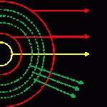
Figure 4: Graphic showing import parameters including the focus distance, number of ranges, and the minimum and maximum distances.[/wptabcontent]
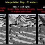
[wptabtitle] INTERPOLATION OPTIONS – MAX EDGE LENGTH[/wptabtitle] [wptabcontent]Max Edge Length (Important): The distance at which points are connected or meshed. Typically 10 x’s or lessthe step or point spacing. A value that is too large can erroneously connect points that should not be connected (Figure 5, left) . Again, this value should be 10’s the Step or less. Decreasing will result in less data being imported (Figure 5, Right).
Figure 5: Example of different max edge length values and the effect of these balues on data import[/wptabcontent]
[wptabtitle] INTERPOLATION OPTIONS – NUMBER OF RANGES[/wptabtitle] [wptabcontent]Number of Ranges: Self-Explanatory. Adjust as needed. Distance between ranges is based on the focus distance.
Min Step: The smallest acceptable step value (typically do not change).
| Focus Distance/Ranges | Interpolation Step | MEL |
| (FD) 10 meters | .01 meter | .1 (or less) |
| (Rng 1) 20 meters | .02 meters | .2 |
| (Rng 2) 40 meters | .04 meters | .4 |
| (Rng 3) 80 meters | .08 meters | .8 |
For each range extending out from the scanner, the interpolation step and max edge length double.
Remember to always hit the Reset button when importing a new scan. Most of the time, the default import values work well. Occasionally, the max angle or max edge length will need to be adjusted. Once imported, a scan is now comprised as a collection or group of sub scans or images. Note the scans now have “surface information” and are no longer point clouds.[/wptabcontent]
[wptabtitle] CONTINUE TO…[/wptabtitle] [wptabcontent]
Continue to Registering Scans in Polyworks V11 IMAlign
[/wptabcontent] [/wptabs]


