Rapidform, offered by Inus Technology, Inc., is 3D scan data processing package ideal for product redesign, inspection, and reverse engineering applications. Rapidform offers three primary packages for data processing including XOS (Scan), XOR(Redesign) , and XOV(Verifier). This document discusses the basic interface and operations in XOR (XOS and XOV are very similar).
Mouse Button Functionality
The standard mouse button functionality for Rapidform is as follows:
Left: Rotate
Middle: —
Right: Rotate
Ctrl + Left or Right: Pan
Shift + Left or Right: Zoom
Zooming Center: Screen Center
Rapidform also offers six other software profiles for navigating including profiles for Solidworks, UGS/NX, Polyworks, Geomagic, CATIA, and ProE Wildfire. Users coming from one of these applications, can choose the application profile that they are most used to working with. The user can also adjust the zooming center for scrolling to be either screen center or mouse position.
Note: If you cannot navigate around in a scene, chances are you are in Selection mode. To toggle between navigation mode (indicated by the two rotating arrows icon) and selection mode (indicated by the crosshairs icon), tap the middle mouse button. This is a key functionality for viewing data in XOR.
Global Vs. Local Mode
By default when you open Rapidform, the scene is automatically in global mode. When in global mode, you cannot directly edit or create a new dataset. To edit a dataset, select the dataset file name in the table of contents (TOC) and then click on the button that indicates the type of dataset you are working with in the menu bar across the top of the screen. For example, if you are working with a mesh, select the file name in the TOC and then select the Mesh button ![]() in the menu bar. You are now in local mesh mode and are presented with numerous mesh editing functions in the new menu bar. Notice when you change from global model to local mode, the primary tool bar changes to include the editing functions specific to the dataset that you are working with.
in the menu bar. You are now in local mesh mode and are presented with numerous mesh editing functions in the new menu bar. Notice when you change from global model to local mode, the primary tool bar changes to include the editing functions specific to the dataset that you are working with.
![]()

Figure 1 (Top): Global Mode Toolbar (Bottom) Local mode for Mesh Datasets that displays available mesh editing tools
Once in local mode, you can perform any number of edits to your dataset. For example, with a mesh dataset you can perform color correction, hole-filling, smoothing and a host of other mesh editing operations. When you are done with an editing session, it is important to close the editing session by either clicking on the Mesh button ![]() again or by selecting the ‘check’ at the bottom right of the screen.
again or by selecting the ‘check’ at the bottom right of the screen.
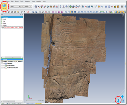
Figure 2: Click either the Mesh button or the ‘check’ to exit local mode
Once you exit local mode, be sure and save your dataset to save the recent changes.
Important Note: You cannot save your project when you are in a local editing session. When you do, you will receive the following warning
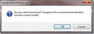
If you click ‘OK’, all changes/edits will be lost and the scene will automatically return to global mode. Boo! Instead if you prefer to keep the recent edits, click cancel, exit local mode by using the methods described above and then save your project.
Selection Tools
To be able to select a portion of a dataset in XOR, the user has to be in local mode for the data type that he/she is working with. To enter local mode for a mesh dataset for example, select the mesh dataset in the table of contents, and then select the Mesh button at the top left of the screen. Once in local mode, the user taps the middle mouse button once to enter selection mode. Once in selection mode, the user can perform a sub-selection using one of the different tools shown below.
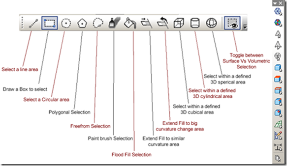
Figure 3 (Left) Selection tools and (Right) Selection filters available in XOR
The freeform tool gives the user the most control over their selection. The paint brush tool is particularly nice for interactive selection and the flood fill selection is great for selecting areas with similar characteristics. Also to append a selection or deselect, the user simply holds the Shift or Ctrl keys respectively. In addition, XOR offers a number of selection filters that allow the user to specify selection for certain data types (i.e. mesh faces, vertices, surface bodies, etc..).
Scene Display Options
The primary scene display options in Rapidform are accessed by selecting the Display tab just under the table of contents at the bottom left of the screen.
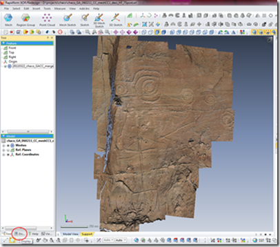
Figure 4: Location of Display tab in Rapidform
In the display settings, users are presented with numerous options for controlling the display of objects in a scene. An image with descriptions of the primary display settings are shown below. Within the display settings, the user can control the number of lights and lighting direction as well as set up a view clipping plane if desired. It is also worthwhile to explore the different mesh shading methods that are available and determine which is the optimum for viewing your mesh data. Toggling image texture off/on also reveals a lot about the surface topography of an object. Take a moment and familiarize yourself with the different display options.
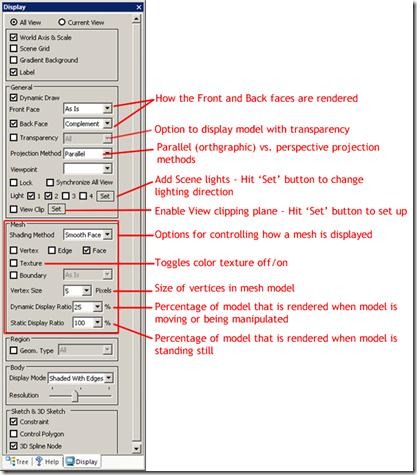
Figure 5: Display tab settings
Note: The mesh display options as well as scene lighting and clipping plane options are also found under the main View menu.
You should now be familiar with the basics of the Rapidform XOR interface. Open your dataset and get started!