This workflow will show you how set up the Breuckmann SmartScan HE prior to beginning your scanning project. Hint: You can click on any image to see a larger version.
[wptabs style=”wpui-alma” mode=”vertical”] [wptabtitle] FOV[/wptabtitle] [wptabcontent]The SmartSCAN HE is a dual camera white light scanner that uses fringe projection to measure precise 3D coordinates. The unit owned by CAST is a 5 MP(megapixel) system that captures color and includes three lenses or fields of view (FOV): 125mm, 475mm, and 825mm. The field of view measure is the length along the diagonal of the scan-able area (shown in Figure 1 below).
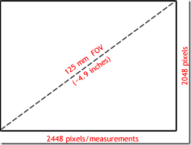
Figure 1: Approximate scan area using 125mm FOV with Breuckmann scanner
A good way to remember the different lens sizes is:
– 125mm: baseball/softball size scan area
– 475mm: basketball size
– 825mm: two basketballs or yogaball size
[/wptabcontent]
[wptabtitle] SIZE OF ARRAY[/wptabtitle] [wptabcontent]The size of the array – 5MP (2448×2048) is static for each of the fields of view. Scanning with the 125mm lens will provide 5,013,504 measurements across the area the size of a softball while scanning with the 475mm lens provide the same number of measurements across the area the size of a basketball. Therefore, a smaller FOV = higher data resolution. The approximate resolution for each of the lenses is provided in the table below:
| Breuckmann Lens/FOV | Estimated Data Resolution (in microns) |
| 125 | 60 |
| 475 | 280 |
| 825 | 500 |
It is important to choose an appropriate lens for your scan project. The size of the object, the desired resolution, the final product for the project, and the amount of time available to scan are all important factors to consider.[/wptabcontent]
[wptabtitle] SETTING UP THE BREUCKMANN[/wptabtitle]
[wptabcontent]
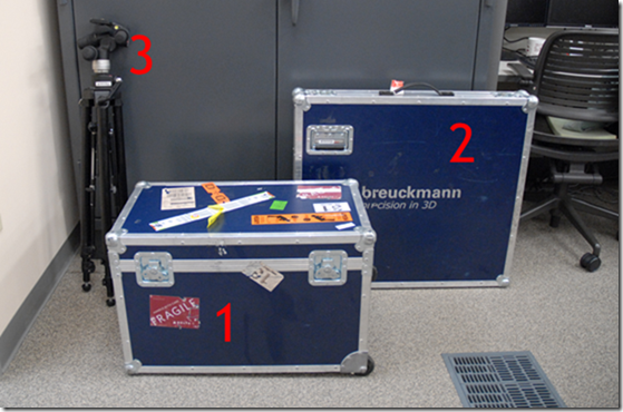
The Breuckmann setup includes three items: the scanner case(1), the calibration chart case(2), and the tripod(3).
Figure 2: (1) Case containing scanner, optolink, and all necessary cables, (2) Case containing large calibration chart, (3) System tripod
At minimum the scanner case and tripod are necessary for every scan project. It is recommended to calibrate the scanner every time the lenses are changed on the scanner. If you are using the mid (475mm) or large (825mm) FOV’s, then you will need to calibrate the system using the large calibration chart in case #2. The calibration chart for the small (125mm) FOV is in the main scanner case. Please see the workflow on Calibrating the Breuckmann for more information on system calibration.[/wptabcontent]
[wptabtitle] TRIPOD SETUP[/wptabtitle]
[wptabcontent]When setting up the Breuckmann, first setup the system tripod. While it is not required for the tripod to be level for scanning objects, it should be level when performing a system calibration. The tripod that is used has four levels on it (shown below). When leveling the tripod, it is best to first level the very base of the tripod (level#1) and then to level the tripod mount using the very top level (level #2). The other levels are not used.
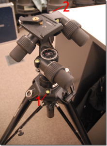 Figure 2: Tripod levels. Only use levels 1 and 2 when leveling the tripod.
[/wptabcontent]
[wptabtitle] CONTENTS OF CASE[/wptabtitle] [wptabcontent]Next open the Breuckmann case, and remove the large piece of t-shaped foam. The case components are shown in the image below.
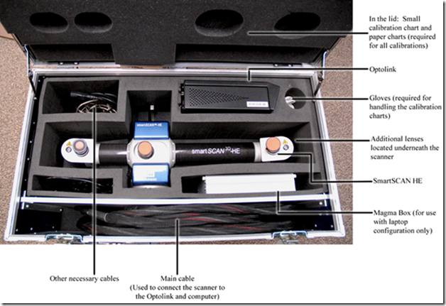 Figure 3: Scanner components in main scanner case
[/wptabcontent]
[wptabtitle] PLACING ON TRIPOD[/wptabtitle]
[wptabcontent]Next, remove the scanner from the case and place on the tripod.
IMPORTANT: The lever on the tripod will click into place once the scanner is secured. Do NOT LET GO of the scanner until you have heard the tripod mount click. Also, always use the silver handle located on top of the scanner when moving the scanner from the box to the tripod or vice versa.
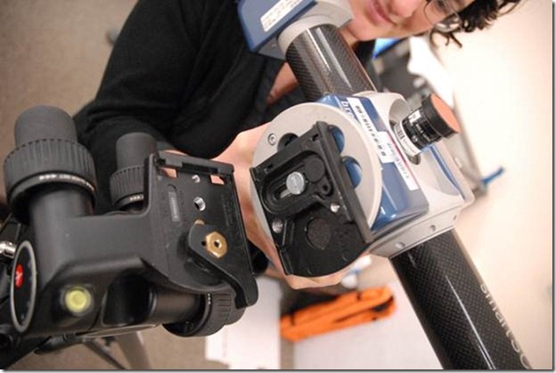
Figure 4: Placing the scanner onto the tripod
[/wptabcontent]
[wptabtitle] LENSES[/wptabtitle]
[wptabcontent]
Once the scanner is on the tripod, next choose the appropriate lenses for your project. Each set of lenses include one lens for the left camera, one lens for the right camera, and one lens for the projector. When looking at the lenses, the first set of letters indicate whether the lens is for the left camera (CL), the right camera (CR) or the project (P) and the last set of numbers indicate the FOV (12 = 125mm, 47 = 475mm, and 82 = 825mm). Notice the labels on the set of lenses below for the 825mm FOV.
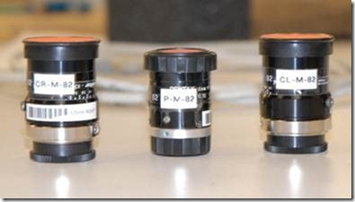
Figure 5: Set of lenses for the 825mm FOV (CR = Camera Right, P=Projector, and CL = Camera Left)
One set of lenses will already be in place on the scanner. If you have to change the lenses, the additional lens sets are located under the pieces of foam directly under the scanner in the case. Before removing the lenses from the scanner, make sure the orange lens caps are in place and locate the black lens caps in the case that are used for the other side of each lens. Unscrew a lens from the scanner and IMMEDIATELY place the black lens cap on the other side of the lens. Repeat for all lenses and place each lens in the individual pieces of bubble wrap provided in the case. BABY THE LENSES as they are a crucial part of the system and can easily be scratched.
When standing behind the scanner, the projector is the center lens the left camera is to left (and farthest from the projector) and the right camera is to the right (closest to the projector). When installing new lenses it is critical to get the correct lens in the correct location. All lenses should be tightly screwed in.
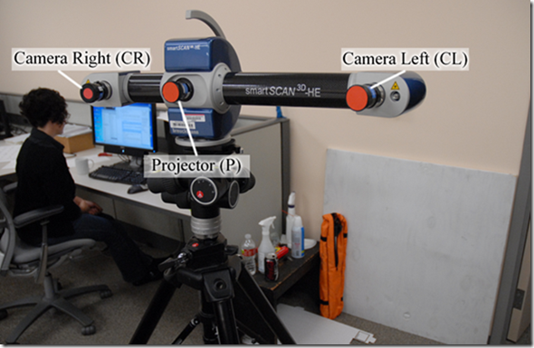
Figure 6: Camera and projector locations on the SmartSCAN
[/wptabcontent]
[wptabtitle] INTERFACING SCANNER WITH A DESKTOP COMPUTER (IN LAB)[/wptabtitle]
[wptabcontent]
Once the scanner is setup, remove the Optolink (black box) and all necessary cables. The large black cable connects the scanner to the Optolink (via the main connector) and the computer (via two firewire connections). The Optolink has its own power cable and is also connected to the computer (via USB).
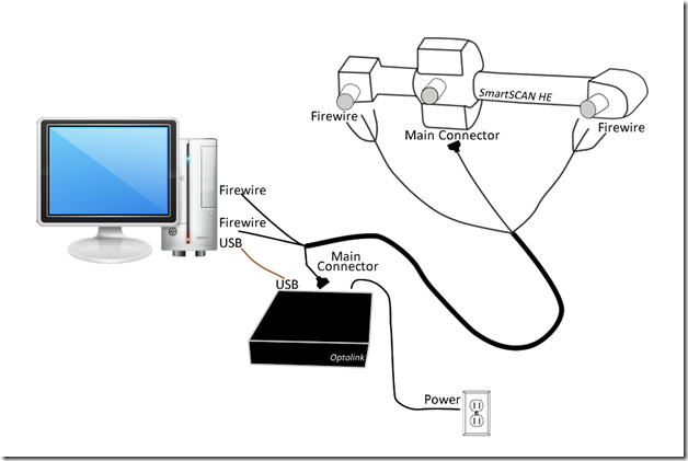
Figure 7: Diagram showing connectivity between SmartSCAN, Optolink box, and desktop computer
Connect the main connector to the scanner. Make sure the connection is square and screw in to secure (Note: Screws should go in easily. If not, you might be cross-threading the connection). Each camera has three cables. Be sure and line up the dots on the smallest round connection (1). Plug the remaining cables in accordingly and be sure to screw in the firewire connections using the screwdriver provided in the case. DO NOT FORCE ANY CONNECTIONS!!!
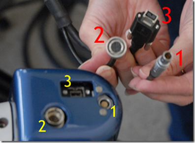
Figure 8: Three camera cables and their associated connections
When plugging cables into the scanner, it is essential to lift the cable slightly and attach it to the scanner handle using the attached Velcro strap. This prevents the weight of the cable from straining the connections.
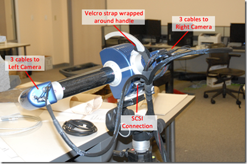
Figure 9: Completed scanner setup with Velcro strapped secured around handle for support
Next, take the opposite end of the black cable and plug the main connector into the Optolink and the two firewires into the back of the desktop. Again, use the provided screwdriver to secure the firewire connections. Finally, connect the Optolink to the desktop using the brown, reflective USB cable and plug the power cord for the Optolink into an outlet. The scanner and associated hardware are now ready to use. Power the Optolink first and then the computer. You are now ready to open the Optocat software and begin your scan project.[/wptabcontent]
[wptabtitle] INTERFACING THE SCANNER WITH A LAPTOP (IN FIELD)[/wptabtitle]
[wptabcontent]
The Dell M4500 laptop is the currently the only CAST laptop that is configured to interface with the Breuckmann. The Magma box (silver box) is an additional piece of hardware that is required to connect the laptop with the scanner. Remove the Magma box, Optolink, and all associated cables from the scanner case. The difference between the laptop configuration and desktop configuration is that the two receiving firewire cables plug into the Magma box and the Magma box connects to the laptop using a express card adapter.
The large black cable connects the scanner to the Optolink (via main connector) and the magma box (via two firewire connections). The Optolink has its own power cable and is connected to the computer (via USB). The Magma box also has its own power cable and it connected to the computer via an express card adapter that fits into the express slot on the left side of the laptop.
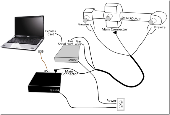
Figure 10: Diagram showing connectivity between SmartSCAN, Optolink, Magma box, and laptop
Connect the main connector to the scanner. Make sure the connection is square and screw in to secure (Note: screws should go in easily. If not, you might be cross-threading the connection.) Be sure and line up the dots on the smallest round connection (1). Plug the remaining cables in accordingly and be sure to screw in the firewire connections using the screwdriver provided in the case. DO NOT FORCE ANY CONNECTIONS!!!
When plugging cables into the scanner, it is essential to lift the cable slightly and attach it to the scanner handle using the attached Velcro strap. This prevents the weight of the cable from straining the connections. The finished setup for the scanner can be seen in the Figure 9 above.
Next, take the opposite end of the black cable and plug the main connector into the Optolink and the two firewires into the Magma box. Again, use the provided screwdriver to secure the firewire connections. Next, connect the Optolink to the desktop using the brown, reflective USB cable and plug in the power cord for the Optolink. Finally, connect the Magma box to the computer using the serial cable and Express Card adapter and plug in the power cord for the Magma box.
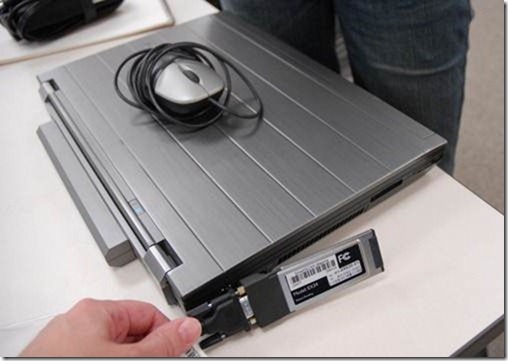
Figure 11: Express card adapter that fits the Express card slot on the laptop
The scanner and associated hardware are now ready to use. Power the Optolink and then turn on the computer. You are now ready to open the Optocat software and begin your scan project.[/wptabcontent]
[wptabtitle] BREUCKMANN DISASSEMBLY[/wptabtitle]
[wptabcontent]
Disassembling the scanner is fairly straight forward with a few notable points. All screwed-in connections including the main connector and all firewires should be unscrewed completely and then pulled. Of the three camera cables, the smallest round connection (1) can be disconnected simply by pulling firmly on metal grips. The large round connection (2) is push-pull connector, so first slide the metal grips forward and then pull to disconnect.
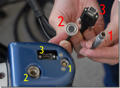
Figure 12: Image showing three cables/connections for each camera
To remove the scanner from the tripod, pull the silver lever on the tripod mount back to disengage the connection and to remove the scanner. Always carry the scanner by the silver handle.
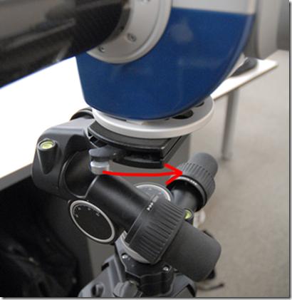
Figure 13: Pull silver lever towards the back of the scanner to remove the scanner from the tripod
Once everything is in the case, double check that all cables/connections are tucked securely in the case before closing the lid.
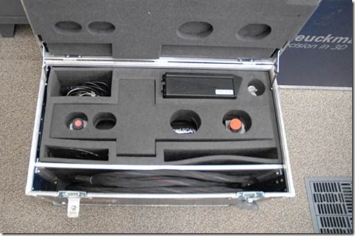
Figure 14: Successful pack up! (Minus the Magma box)[/wptabcontent] [/wptabs]
