[wptabs style=”wpui-alma” mode=”vertical”]
[wptabtitle] MANUALLY IDENTIFYING FEATURE POINTS PT 1[/wptabtitle]
[wptabcontent]
Manually Identifying Feature Points
If the automatic Extract and Identify Feature Points operation did not work or if you need to add additional feature points to a scan to get better results (and less error), then you will need to manually add a few feature points to a scan and its associated images.
1. First, click the Passpair Definition button ![]() on the Color Toolbar. Immediately, you should see all of the points in the 2D View identified from that automatic feature point extraction. If you select an image from the TOC and open it, you will also see feature points in the image. The key to good color mapping is it have feature points in all/most of your images. When you have a scan that is a large %age sky then it can often be difficult for the automatic feature point extraction to execute. Therefore, you will want to place points in areas where you would like to see an improvement of the color mapping (areas that were not mapped well initially) and you also want a good distribution of points across all of your images where points can be easily identified.
on the Color Toolbar. Immediately, you should see all of the points in the 2D View identified from that automatic feature point extraction. If you select an image from the TOC and open it, you will also see feature points in the image. The key to good color mapping is it have feature points in all/most of your images. When you have a scan that is a large %age sky then it can often be difficult for the automatic feature point extraction to execute. Therefore, you will want to place points in areas where you would like to see an improvement of the color mapping (areas that were not mapped well initially) and you also want a good distribution of points across all of your images where points can be easily identified.
2. By default when you open the Passpair Definition options the 2D Zoom Windows will automatically open for the scan in the 2D View and also for an image that you open. To effectively use the 2D zoom window in the 2D View (Gray View) change the Selection Mode from Rectangular to Point by clicking on the button several times until it changes from ![]() to
to ![]() . [/wptabcontent]
. [/wptabcontent]
[wptabtitle] MANUALLY IDENTIFYING FEATURE POINTS PT 2[/wptabtitle]
[wptabcontent]Now as you click and drag your mouse around the 2D View the view changes in the 2D View.
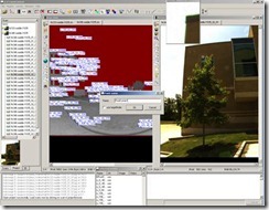
3. Now identify some prospective Feature points between a scan and its images. Drag the mouse in the 2D view to identify a Feature point location in the Zoom View – click on the point in the Zoom view and Name it (something that is easy to remember). Now identify the same point in the image view – Click on it (using the Zoom View) and give it the EXACT SAME NAME (copying and pasting the name often works best here). Now, check all of the images to see if the same point is identifiable in any other image, if so select the image, identify the point and give point the SAME NAME.
Figure 5: Process of identifying and naming manually identified points.
4. Rinse and repeat.
5. Once you have identified all of the manual feature points (3-10), click the calculate extrensics button ![]() to calculate the external calibration file.
to calculate the external calibration file.
6. Note the error and Generate Color Scans to view the results. Verify the quality of the results and proceed as necessary.
[/wptabcontent]
[wptabtitle] CONTINUE TO…[/wptabtitle]
[wptabcontent] If you are satisfied with the quality of your results, continue to Z+F Laser Control: Filtering and Exporting Your Data[/wptabcontent] [/wptabs]
