I. Introduction
A. Comparing two meshes is a common task in 3d modeling applications. A model created from laserscanning data might be compared with a model created from photogrammetric data to assess relative accuracy. A building’s façade might be documented with a laserscanner at six month intervals to monitor erosion by comparing the meshes and individual profiles over time. This workflow demonstrates how to carry out a comparison in Rapidform XOR.
II. Aligning Models
A. Models with surveyed targets
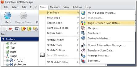
1. In the Main Menu in Rapidform go into Tools > Scan Tools > Align between Scan Data.
Fig. 1: Align between Scan Data Menu
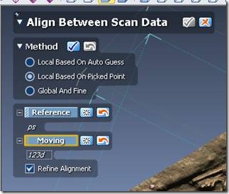
2. Select the Local Based on Picked Point method and select your Reference and Moving targets- the two meshes you are trying to align.
3. Check the box to Refine Alignment.
Fig. 2: Select reference and moving meshes
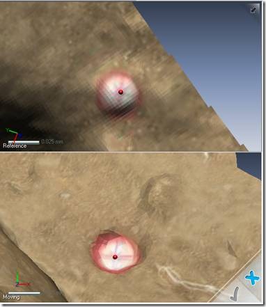
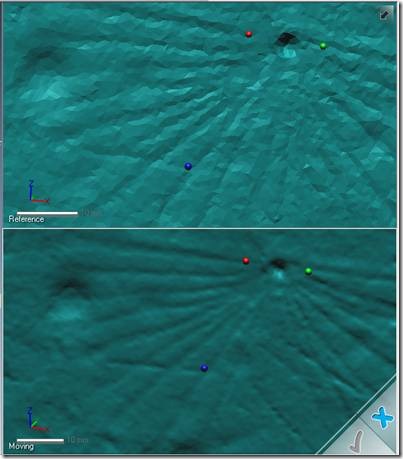
4. Zoom in close to each target and select it, first in the Reference and then in the Moving model. Right click to toggle between zooming and selection modes. Be sure to select the center of the target as accurately as possible. A colored pin will appear showing the picked center of each target
Fig. 3: Pick point on corresponding targets in the moving and reference meshes.
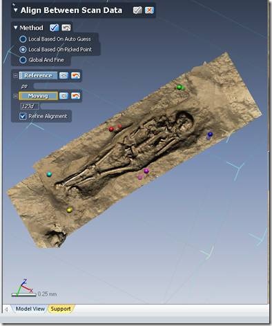
5. Once all the targets have been matched, you can visually review the goodness of the fit between the models by looking at the distance between the pins shown in the left hand window in this menu. When you are satisfied, check the Align Between Scan Data box to complete the process. The alignment will be refined.
Fig. 4: When the meshes are aligned, complete the transformation.
B. Models without targets
1. Aligning models without targets is inherently less accurate than alignments done based on surveyed targets because points on natural surfaces must be matched. Because the natural surfaces -as they are modeled- have slight local deviations, the algorithms used for fitting the models together can encounter problems.
2. The process is essentially the same as aligning models with surveyed target, but with the additional requirement of selecting good targets on natural surfaces to achieve a closely aligned match. Follow the instructions in A1, A2 and A3.
3. Select points with high local curvature – edges and corners ideally- or intersections of linear features. Try to pick at least six points. When you are satisfied, check the Align Between Scan Data box to complete the process. The alignment will be refined.
Fig.5: On natural surfaces pick points on well defined features.
III. Assessing Differences between two Meshes
A. Mesh Deviations
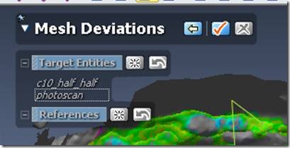
1. In the Main Menu in Rapidform, select Measure > Mesh Deviations.
2. Select the meshes you are interested in as the Target Entities.
Fig. 6: The Mesh Deviations Menu
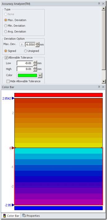
3. On the right hand side of the screen, set the Allowable Tolerance as the acceptable deviation between the meshes. Adjust the Color Bar to reflect the expected range of deviations between the meshes. Under Type select the appropriate deviation for your application, Max. Deviation is recommended for erosion monitoring. Click the ! under Deviation Option to recalculate the range.
Fig. 7: Properties of a mesh deviations map
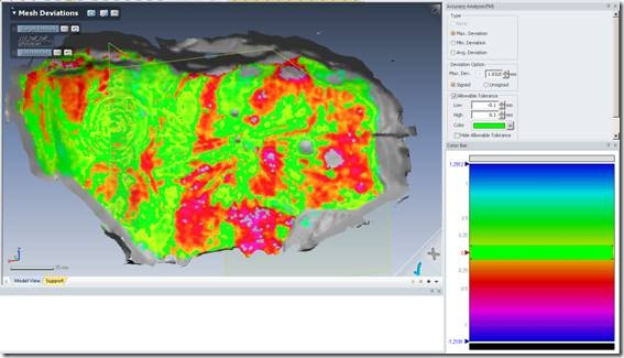
4. Click the right arrow button in the Mesh Deviations menu to show the deviation overlaid on the mesh
Fig. 8: Mesh deviations displayed over the mesh.
