In this series, columns in a deteriorating colonnade will be modeled by several methods.
Hint: You can click on any image to see a larger version.
[wptabs style=”wpui-alma” mode=”vertical”] [wptabtitle] USE THE CLOUDWORX SLICE TOOLBAR[/wptabtitle]
[wptabcontent]Method 2: Slicing Single Cross Section and Revolving the Profile Around Center – Similar to the first method, the column will be sliced and traced; however here, a single profile will be traced and revolved around the center, creating a solid or surface object. Follow steps in Method 1, Section I for setting up the ACAD model space and isolating the colonnade.
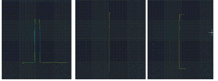
I. Use the CloudWorx Slice Toolbar to slice the point cloud from the top view (or whichever view allows you to see the entire diameter of the column/feature); this will be the only section profile that will be traced and we will only be tracing half of it; choosing the most complete/intact slice possible is recommended. See Method 1 for details on slicing
Figure 7 (Left) Top view of the column; magenta lines highlight the slicing boundaries – (Center) Top view of the column profile slice – (Right) Front view of the column profile slice[/wptabcontent]
[wptabtitle] TRACE THE PROFILE AND SNAP TO POINT CLOUD[/wptabtitle]
[wptabcontent]
II. Trace the profile of the section cut, snapping directly to point cloud > Front or Side View > Make correct layer current > Zoom in to view points comfortably and refresh point cloud to confirm all points visible ![]() (do this periodically, especially when zooming in/out) > Command Line: PL or POLYLINE and begin to trace the profile/outline the profile of the section cut
(do this periodically, especially when zooming in/out) > Command Line: PL or POLYLINE and begin to trace the profile/outline the profile of the section cut
REMEMBER: (1) Enable OSNAP “NODE” to snap to points (2) At command line: type “U” during active polyline command to undo vertices/go back without ending the command (3) At command line: PEDIT allows polyline(s) to be edited, joined, etc. (4) See ACAD Help: Drawing and Editing Polylines for more information
[/wptabcontent]
[wptabtitle] DETERMINE CENTER AROUND WHICH TO ROTATE[/wptabtitle] [wptabcontent]III. Determine the center around which to rotate > NOTE: there are a variety of ways to determine the center of a feature; one is outlined here. Also see the “fit pipe to cloud” method (following section), which determines the center directly from the point cloud and places a polyline along the centerline >
A. After half of the profile has been traced turn on ORTHO mode, which restricts drawing to a 90-degree vertical and horizontal direction to ensure clean angles for the rotation later ![]()
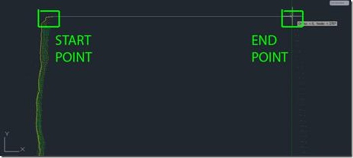
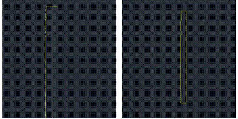
B. OSNAPS – enable ENDPOINT and MIDPOINT -> Use ONSNAPS to draw a line that is perpendicular to the column’s profile polyline: the start point snaps to the endpoint of the top of the column and the end point snaps to the point cloud on the opposite edge of the section cut – this line represents the full diameter of the column. Draw another line in the same way at the bottom of the column (See Figures 12 & 13)
Figure 8 (Left) Front view of point cloud and polyline representing left profile of the column – (Center) Front view with the point cloud hidden – (Right) Original polyline with perpendicular lines drawn at the top and bottom representing the diameter of the column[/wptabcontent]
[wptabtitle] EXAMPLES[/wptabtitle]
[wptabcontent]
Figure 9 – Front view, close-up of the top of the column; on the left of the image, the yellow polyline is the original line tracing the point cloud profile (dense green points). With osnaps, draw a line snapping to the end point of the original polyline. Ortho Mode ensures a perpendicular line to the opposite edge of the point cloud/column (less dense green dots on the right side of the image). Repeat this process at the bottom to achieve the 3 lines shown in Figure 8.[/wptabcontent]
[wptabtitle] USING OSNAPS[/wptabtitle] [wptabcontent]
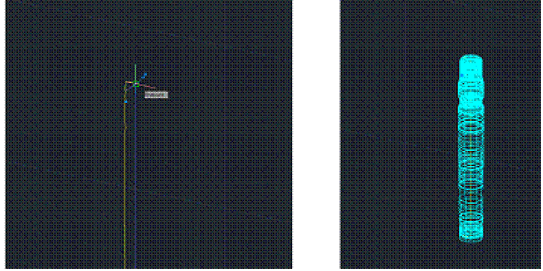
C. Use OSNAPS to snap to the midpoint of the line at the top of the column to the midpoint of the line at the bottom of the column – this line represents the center of the column (TIP: When snapping to midpoint, a triangle and the word “midpoint” appears near the cursor) -> Use grips or the TRIM command to trim the ends of the lines that protrude past the center line
NOTE: This method finds the center based on the diameter of the column at the top and bottom at the point of the slice, accounting for any leaning/tilting along the z-direction; For generally upright features, drawing a line in the center and restricting it to the z-axis will result in more regularized features with identical “up directions”
IV. Command line: PEDIT to edit the polylines and join them into a single closed polyline > PEDIT > Select original polyline > JOIN > Select centerline, top line, and bottom line > ENTER 2X > Clicking on the polyline should confirm that it is now a single object (if it does not join, check to confirm no endpoints are snapped to one another but they are NOT overlapping).
Figure 10 (Left) Draw a polyline from the midpoint of the top line to the midpoint of the bottom line – note the yellow triangle and ‘midpoint’ showing the OSNAP constraint is active (Right) Polylines have been drawn, trimmed, and joined to form a single polyline representing the profile of the column from the center to the edge[/wptabcontent]
[wptabtitle] ROTATE PROFILE TO FORM 3D OBJECT[/wptabtitle]
[wptabcontent]V. Rotate profile to form 3D object > Create and make a separate layer for the 3D object and make it active > 3D Modeling main toolbar > EXTRUDE tab pulls down to REVOLVE (see figure 4) or at command line: REVOLVE > select profile polyline > ENTER > “Specify Start point or define axis” > Select endpoint at the bottom of the centerline > “Specify axis endpoint” > Select endpoint at the top of the centerline > “Specify angle of revolution” > ENTER to accept default of 360-degrees
6. Modeled object can now be edited or exported as desired.[/wptabcontent]
[wptitle]CONTINUE TO…[/wptabs]
[wptabcontent]Continue to Comparing Modeled Objects to Original Points[/wptabcontent]


