This series will show you how to create 3d models from photographs using Agisoft Photoscan and Esri ArcGIS.
Hint: You can click on any image to see a larger version.
Many archaeological projects now use photogrammetric modeling to record stratigraphic units and other features during the course of excavation. In another post we discussed bringing photogrammetric or laserscanning derived models into a GIS in situations where you don’t have precise georeferencing information for the model. In this post we will demonstrate how to use bring a photogrammetric model for which georeferenced coordinates are available, using Agisoft’s Photoscan Pro and ArcGIS.
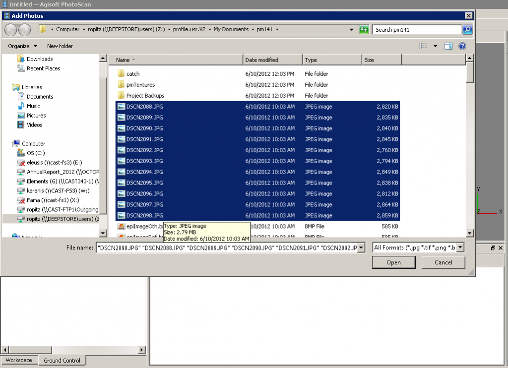
[wptabs mode=”vertical”] [wptabtitle] Load Photos[/wptabtitle] [wptabcontent]Begin by adding the photos used to create the model to an empty project in Photoscan.
[/wptabcontent]
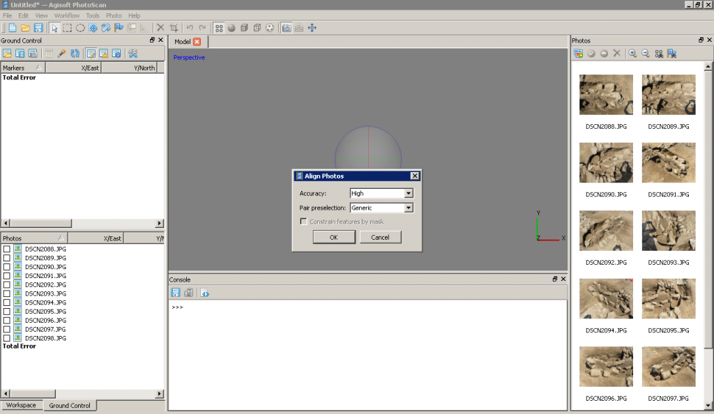
[wptabtitle] Align Photos[/wptabtitle] [wptabcontent]Following the Photoscan Workflow, next align the images. From the menu at the top choose ‘Workflow’>’Align Images’. A popup box will appear where you can input the alignment parameters. We recommend selecting ‘High’ for the accuracy and ‘Generic’ for the pair pre-selection for most convergent photogrammetry projects.
[/wptabcontent]
[wptabtitle] A choice[/wptabtitle] [wptabcontent]At this point there are two approaches to adding the georeferenced points to the project. You can place the points directly on each image and then perform the bundle adjustment, or you can build geometry and then place the points on the 3d model, which will automatically place points on each image, after which you can adjust their positions. We normally follow the second approach, especially for projects where there are a large number of photos.
[/wptabcontent]
[wptabtitle]Build Geometry[/wptabtitle]
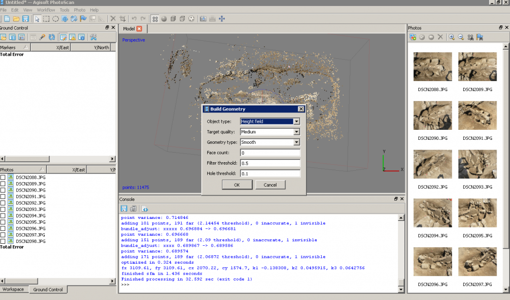
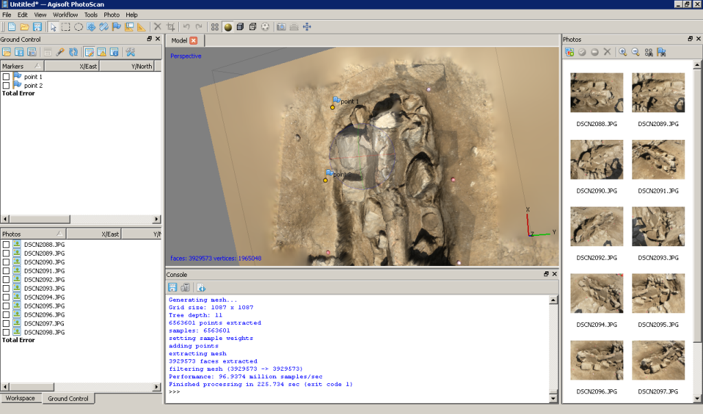
[wptabcontent]Under ‘Workflow’ in the main menu, select ‘Build Geometry’. At this point we don’t need to build an uber-high resolution model, because this version of the model is just going to be used to place the markers for the georeferenced points. A higher resolution model can be built later in the process if desired. Therefore either ‘Low’ or ‘Medium’ are good choices for the model resolution, and all other parameters may be left as the defaults. Here we have selected ‘Medium’ as the resolution.
[wptabtitle]Get the georeferenced points[/wptabtitle]
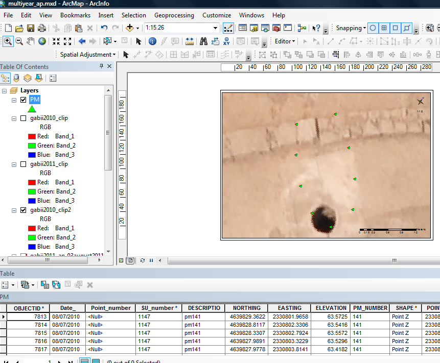
[wptabcontent]When the photos for this model were taken, targets were places around the feature (highly technical coca-cola bottle caps!) and surveyed using a total station. These surveyed targets are used to georeference the entire model. In this project all surveyed and georeferenced points are stored in an ArcGIS geodatabase. The points for this model are selected using a definition query and exported from ArcGIS.
[wptabtitle]Add the georeferenced points[/wptabtitle]
[wptabcontent]On the left you have two tabbed menus, ‘Workspace’ and ‘Ground Control’. Switch to the the ‘Ground Control’ menu. Using the ‘Place Markers’ tool from the top menu, place a point on each surveyed target. Enter the corresponding coordinates from the surveyed points through the ‘Ground Control’ menu. Be careful to check that the northing, easting and height fields map correctly when importing points into Photoscan, as they may be in a different order than in ArcGIS.
[wptabtitle]Local coordinates and projections[/wptabtitle]
[wptabcontent] In practice we have found that many 3d modelling programs don’t like it if the model is too far from the world’s origin. This means that while Photoscan provides the tools for you to store your model in a real world coordinate system, and this works nicely for producing models as DEMs, you will need to use a local coordinate system if you want to produce models as .obj, .dae, .x3d or other modeling formats and work with them in editing programs like Rapidform or Meshlab. If your surveyed coordinates involve large numbers e.g. UTM coordinates, we suggest creating a local grid by splicing the coordinates so they only have 3-4 pre decimal digits. [/wptabcontent]
[wptabtitle]Bundle Adjust – Another Choice[/wptabtitle]
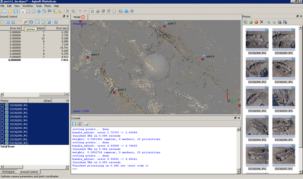
[wptabcontent]After all the points have been placed select all of them (checks on). If you believe the accuracy of the model is at least three time greater than the accuracy of the ground control survey you may select ‘update’ and the model will be block shifted to the ground control coordinates. If you believe the accuracy of the ground control survey is near to or greater than the accuracy of the model, you should include these points in your bundle adjustment to increase the overall accuracy of the model. To do this select ‘optimize’ from the ‘Ground Control’ menu after you have added the points. After the process runs, you can check the errors on each point. They should be less than 20 pixels. If the errors are high, you can attempt to improve the solution by turning off the surveyed points with the highest error, removing poorly referenced photos from the project, or adjusting the location of the surveyed points in individual images. After adjustments are made select ‘update’ and then ‘optimize’ again to reprocess the model.
[wptabtitle] Continue to…[/wptabtitle]
Continue to PhotoScan – Building Geometry & Texture for Photogrammetry
[wptabcontent]
[/wptabs]
