This document guides you through scanner settings and collection procedures using the Konica-Minolta Vivid 9i, a turntable and Polyworks IMAlign software.
Hint: You can click on any image to see a larger version.
[wptabs style=”wpui-alma” mode=”vertical”] [wptabtitle] CALIBRATION [/wptabtitle]
[wptabcontent]
1. White Balance Calibration: Before you begin scanning, you need to perform the white balance calibration on the scanner. Make sure the lighting conditions in your environment are set to what they will be during the scanning process.
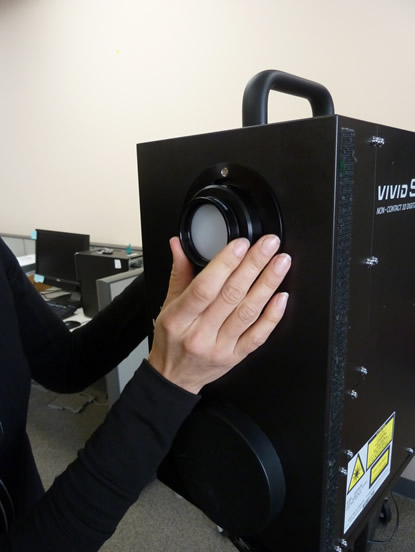
A. Next, remove the white balance lens from the lens box and screw it onto the top front of the scanner.
B. Press the Menu button the back of the scanner and select White Balance and press Enter. Under the White Balance menu, choose Calibration and press Enter. Do not touch or pass in front of the scanner while it is performing the calibration.
C. When the calibration is complete, remove the white balance lens and put it back in the lens box. You are now ready to begin your scanning project.
[/wptabcontent]
[wptabtitle] TITLE OF SLIDE [/wptabtitle] [wptabcontent]
2. Open Polyworks IMAlign (v 10.1 in this example) and select the Plugins menu – Minolta – VIVID 9i – Step Scan. The One Scan option is used if you are not using the turntable. If you do not see the Plugins menu, you will need to install the Plugins Add On from the Polyworks installation directory.
3. When the VIVID 9i window opens, you should see a live view from the scanner camera. Select the Options button on the right. Under Scan Parameters, select Standard Mode. Extended mode offers a greater scan range however it limits noise filtering operations. Standard mode should work for most projects. The number of scans are the number of passes the scanner makes per scan position. From the manual: “It averages the data from each pass to produce a single scan file therefore more scans theoretically will give you the most accurate data. We recommend 3 or 4 scans, however if time constraints are an issue then this number may be lowered.
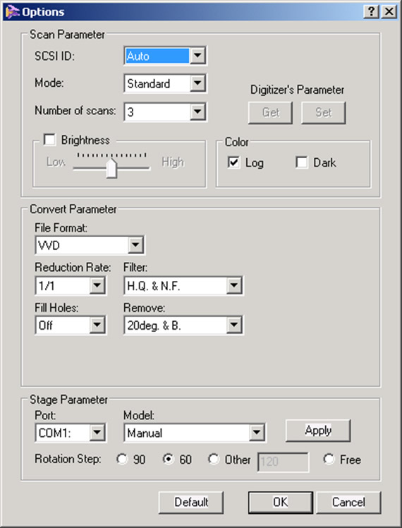
4. Under Convert Parameter, check the VVD File Format and a Reduction Rate of 1/1 (No data reduction). Under filter, select H.Q. & N.F. (High quality and noise filter). This is the highest filter setting and is most effective for minimizing scanner noise. Also, make sure Fill Holes is Off and under Remove, it is generally advised to select 20deg & B. (20 degrees and Boundary). This last parameter removes data around the perimeter of a scan that tends to be less reliable. In previous experiences, it was noted the data around the scan edge often curves up creating an artificial lip in the data. Researchers found that increasing the Remove parameter to the highest setting, removed the “scan edge lip.” All of the settings above are just suggestions and may need to be altered to suit individual project needs.
5. Under Stage Parameter – Model, select Parker 6105 (Fast); this selects the correct turn table model. Finally select the desired Rotation Step. A Rotation step of 60 is suggested which will result in collecting 6 scans per object rotation.
6. Hit Apply and then OK.
7. Back in the VIVID 9i Window, select the Stage Apply button to apply the stage parameters. Next, we will calibrate the turntable by using the black and white calibration charts found in the turntable case.
8. The smaller chart is used with the tele lense and the larger chart is used with both the mid and wide angle lenses. Place the appropriate calibration chart on the system turntable facing the scanner. The smaller chart has two pegs that fit associated holes on the turntable. The larger chart also has two smaller pegs that rest in a recessed ring on the turntable. In either case, it is important for the center of the chart to rest in the center of the turntable and for each chart to be completely upright. The black line that runs down the center of each chart is used to identify the center axis of the turntable which is then used to coarsely align or register the scans from a single scan rotation. In this example, the tele lense and small chart will be used.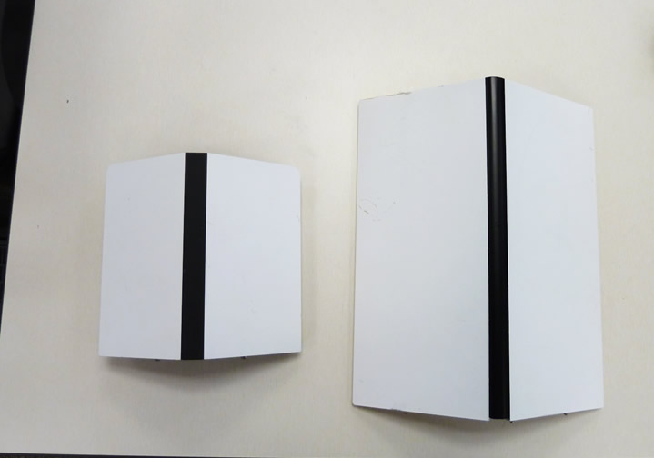
9. You should now see the scanner chart in the live view window. It is recommended to fill the view with the scan chart as best as possible. You may need to adjust the scanner position and rotation to achieve the correct view. NOTE: You will not be able to move the scanner after you perform the turntable calibration. If you do move the scanner after this step, then the turntable will need to be re-calibrated.
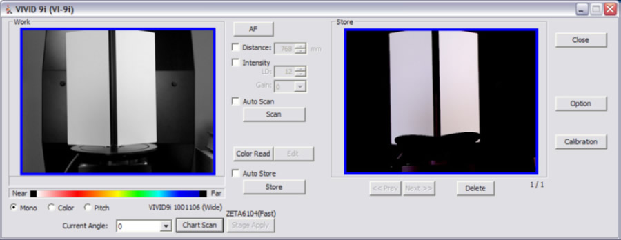
10. Next, hit the Chart Scan button. The scanner will then scan the chart and indicate whether or not the calibration was successful. It is not necessary to store the chart scan.
11. You are now ready to begin scanning. Place the desired object on the center of the turntable. It is advised to perform a single scan to test system perameters before completing a scan rotation. First, select the AF (Auto Focus button). This auto focuses the scanner camera and determines the object’s distance from the scanner, displaying the value in the Distance box. The Distance value can be altered to acquire object data at a specified distance. Next, press the Scan button. Once completed the scan should appear in the Store window on the right. Check the scan for any anomalies such as holes, poor color, etc. If you wish to keep the scan, you MUST click the Store button. If you do not click the Store button, the scan will be overwritten. If you are happy with the scan results, then you are ready to proceed with a scan rotation.
12. To perform a scan rotation, first select the Auto Scan and Auto Store options. Next, press the Scan button. The scanner will perform 6 scans rotating 60 degrees between each scan and will automatically store the results in the IMAlign project. Once the scans are complete, click in the IMAlign project window to view the results.
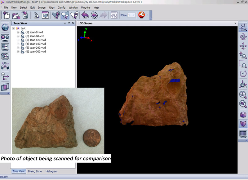
13. The six scans are displayed in the Tree view (table of contents) on the left with the name “scan” followed by a suffix indicating the scan angle (0, 60, 120, etc…) and represent one complete scan rotation. These scans have been roughly aligned to one another based on the central axis of the system’s turntable. We recommend to clean and align scans as you go as it takes little additional time and it ensures that all of the required data has been captured (and all holes/voids have been filled in).
14. Using the middle mouse button, select and delete any data that are not associated with your scan object. Next, make sure all of your scans are unlocked and run a Best Fit alignment. The Best Fit operation is an iterative alignment that produces a more accurate alignment between the scans.
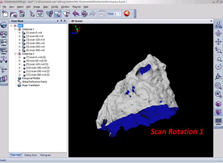
15. Now that the scan rotation has been cleaned and better aligned, prepare for the next scan rotation by first locking all of the scans of the first rotation (select all in the Tree View, right click and select Edit – Lock or use Ctrl+Shft+L) and then by grouping the scans together (select all in the Tree View, right click and select Group). Now observe the data that you have collected, note holes or voids in the digital object, and identify what areas need to be scanned next. If you are scanning a large object, perhaps you will need to perform another scan rotation to acquire more of the object or if it’s a smaller object, perhaps a few single scans are needed in order capture the bottom and top views of the object. Reposition the object on the turntable to prep for the next scan sequence.
16. Next, return to the scan window and complete another scan/scan rotation. In this example, we will complete another scan rotation in order to show how align two rotations to one another.
17. Because the object has been repositioned, it is always good to Auto Focus (press the AF button) before each scan/scan rotation. Complete the second scan or scan rotation.
18. In the IMAlign window, you may have to hide the first scan rotation (simply middle click on the group name or right click the name and select View – Hide or use Strl+Shft+D) to more easily view the new data. Go ahead and delete any extraneous data from the scene and group the scans from the second rotation (select all, right click and select Group).
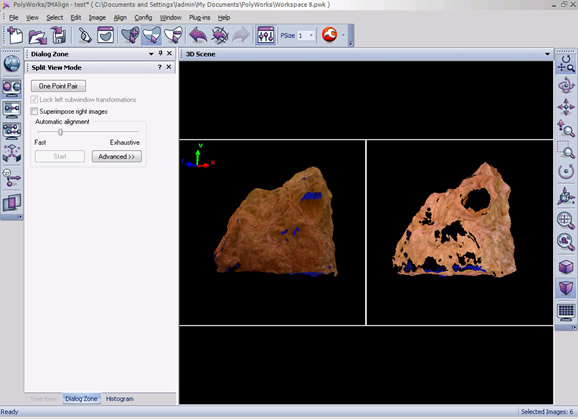
19. To align the second rotation to the first rotation, first unhide the first rotation (middle click the group name or right click and select View – Restore or use Ctrl+Shft+R). Next select the split view alignment button and independly rotate each view so that they are roughly the same perspective of the scan object .
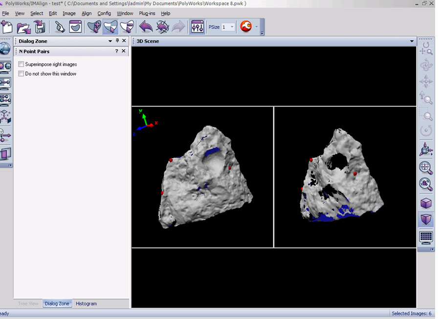
20. Now select the N Point Pairs button (Align Menu – N Point Pairs) and identify at least three pick points between the two views. Right click when complete and you should now see the second rotation roughly aligned to the first. Run a best fit alignment to optimize the alignment and then lock the second scan group. This is a very basic description of alignment in IMAlign, for more detail please refer to the Registering (aligning) Scan in Polyworks IMAlign workflow.

21.
- Complete as many scans/scan rotations that are necessary in order to get a complete digital model of your object. Small holes can be holefilled with additional post processing in IMEdit.
22. Refer to the Registering (aligning) Scan in Polyworks IMAlign workflow for further details on scan alignment and the Creating a Polygonal Mesh using IMMerge workflow for more information on creating a polygonal mesh file in Polyworks.
[/wptabcontent]
[/wptabs]