This document covers scan registration (alignment) and overlap reduction in Polyworks IMAlign.
Hint: You can click on any image to see a larger version.
As objects become more complex, using layers (Shift + L) becomes essential to organizing and controlling the model space.
[wptabs style=”wpui-alma” mode=”vertical”] [wptabtitle] REGISTRATION – 1[/wptabtitle] [wptabcontent]
1. Import all scans into IMAlign. Lock (Ctrl + Shft + L or right click – Edit – Lock) the first scan in the table of contents (TOC).
Note: To hide a scan’s digitizer position, hit the plus next to the scan name in the table of contents, plus next to reference points, then middle click (to hide) the Digitizer Position.
2. Next select a scan in the TOC to align to the first scan and select the Split View Alignment icon![]() to enter Local Mode.
to enter Local Mode.
Note: The two scans have to have areas of overlap in order to be able to align them together. Also, you can only enter Split View Mode when the unlocked scan is selected.
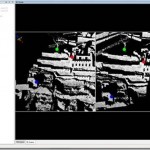
3. Rotate both views so that they are oriented correctly with respect to one another (see Figure 1 below). This is important for identifying common points between the two scans.
[/wptabcontent]
[wptabtitle] REGISTRATION – 2[/wptabtitle] [wptabcontent]
4. Select N Point Pairs Alignment ![]() .
.
5. Match at least 3 pairs of corresponding points between the two views (no more than 5 or so is necessary). Points should be across the entire scan (not concentrated in one area) and multi-planar. Right click when finished.
Figure 1: Identifying common tie points between two scans
6. Next, run a best fit alignment ![]() between the scans. This is an iterative alignment that fine tunes the NtoN alignment. Subsampling should be 1/1; optionally you can choose to Show slipping color map. In the statistics tab, the Standard Deviation reflects the accuracy of the alignment. Ideally (though it doesn’t always happen) you want the standard deviation to be less than the accuracy of the scanner. For the Optech, this is approximately 1 centimeter (.01). For the Minolta VIVID 9i, this varies based on the lense that you use (tele = 200 microns (.2mm), mid = 400 microns (.4mm). If the best fit alignment is taking too long to run but the alignment is close enough (the standard deviation is less than or equal to the accuracy of the digitizer and the Convergence value and mean are very close to 0), then the alignment can be stopped. This accepts the best fit alignment computed up to that point.
between the scans. This is an iterative alignment that fine tunes the NtoN alignment. Subsampling should be 1/1; optionally you can choose to Show slipping color map. In the statistics tab, the Standard Deviation reflects the accuracy of the alignment. Ideally (though it doesn’t always happen) you want the standard deviation to be less than the accuracy of the scanner. For the Optech, this is approximately 1 centimeter (.01). For the Minolta VIVID 9i, this varies based on the lense that you use (tele = 200 microns (.2mm), mid = 400 microns (.4mm). If the best fit alignment is taking too long to run but the alignment is close enough (the standard deviation is less than or equal to the accuracy of the digitizer and the Convergence value and mean are very close to 0), then the alignment can be stopped. This accepts the best fit alignment computed up to that point.
[/wptabcontent]
[wptabtitle] REGISTRATION – 3[/wptabtitle] [wptabcontent]
7. Once the best fit alignment is complete, lock the second scan. Select the next scan to align and repeat Steps 2-6.
8. Once all of the data has been aligned, compute one final Global or Best Fit Alignment. This adjusts the alignment across the entire dataset. To do this, select a single scan that has good coverage across the entire dataset and lock it then unlock all remaining scans. Run the Best Fit Alignment one final time. Once all alignments have been completed, save your IMAlign Project. A recommended naming convention is project_name_GR (GR = Global Registration.
TIP: Scans can also be grouped together allowing you to hide, select and perform numerous operations on a group of scans at the same time. [/wptabcontent]
[wptabtitle] OVERLAP REDUCTION – 1[/wptabtitle] [wptabcontent]
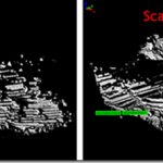
Overlap reduction is performed to remove the overlapping or redundant data between scans. This is recommended prior to meshing and/or to reduce the size of the dataset. Make sure and save a copy of your dataset prior to overlap reduction. Next, select Image – Reduce Overlap.
The Overlap Reduction parameters are discussed more below:
Max Distance: Determined by scanner
Max # of overlapping images: Recommended 5
Number of overlap layers: Recommended 3
Best Data (Std) –Default (when all scans are the same resolution) – typically use this option
Best Data (Extreme) – Used when you have scans of multiple resolutions.
This ensures that high resolution data will not be replaced by overlapping
lower resolution data. Select all high resolution scans in TOC and then run operation.
Suggested Setting: Best Data Standard
[/wptabcontent]
[wptabtitle] OVERLAP REDUCTION – 2[/wptabtitle] [wptabcontent]
Data Quality:
Viewing Angle: Accepts points that are orthogonal to the scan direction (directly in front of the scanner) rather than those that are more oblique.
Point-to-Digitizer Distance: Accepts points that are closer to the scanner rather than those that are further away.
Suggested Setting: Viewing Angle
Sometimes manual overlap reduction is required in addition to the automatic reduction in order to visually clean-up the data. The best way to go about this is by systematically selecting using the Select scan on Screen Tool ![]() and toggling scans (using the Hide and Keep commands) and deleting the redundant data. This is done primarily for visual purposes.
and toggling scans (using the Hide and Keep commands) and deleting the redundant data. This is done primarily for visual purposes.
Once overlap reduction is completed on your project, save your project with a different file name. A recommended naming convention is project_name_GRE (GRE = Global Registration with additional edits/overlap reduction). It is best to save projects with different names at key processing steps, in case one wants to return to a specific processing point.
For more on meshing, see Meshing using Polyworks IMMerge V11.
[/wptabcontent]
[wptabtitle] ALIGNING MULTIPLE IMAlign PROJECTS[/wptabtitle] [wptabcontent]
Aligning Multiple IMAlign Projects
Multiple IMAlign projects can also be aligned to one another. This allows for users to work on different sections of the site and then merge those sections together into one project. A global alignment and overlap reduction should be completed on each individual project before the projects are brought together. When an IMAlign project is imported to an existing project, the screen goes straight into a split view alignment. Align the 2 datasets using N Point pairs and then compute a Best Fit Alignment. Repeat for multiple projects. Multiple datasets can also be aligned in IMInspect if necessary.
[/wptabcontent] [/wptabs]

