This series will show you advanced modeling building modeling techniques using Leica’s Cyclone.
Hint: You can click on any image to see a larger version.
[wptabs style=”wpui-alma” mode=”vertical”]
[wptabtitle] SELECT OBJECT[/wptabtitle]
[wptabcontent]
Note that restoring the original points that are removed when an object is created is essential to placing openings or to creating more complex features within an object.
I. Select Object –> Right Click –> Insert Copy of Object’s Points. Also note that if/when the working ModelSpace is merged back into the original ModelSpace upon closing, all objects and points are merged so any re-inserted points should be considered (most likely deleted) before merging into the original MS.
II. Once the points have been inserted, Align View so that object being modeled is perpendicular to screen (see GMV Guide ‘Model a Non Rectangular Patch’). There are several methods to creating openings, depending on their geometry and whether the opening is repeated:[/wptabcontent]
[wptabtitle] CREATING A SINGLE OPENING[/wptabtitle]
[wptabcontent]
A. Creating A Single Opening:
1. Create primary patch/wall in which hole is to to be made
2. Select Object –> Right Click –> Insert Copy of Object’s Points.
3. Create Fence that is completely inside intended opening
4. Select the primary patch -> Edit Object -> Patch -> Subtract
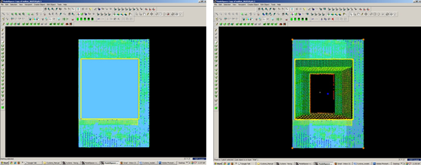
Figure 5 (Left) Primary Patch with copy of points inserted and fence drawn- note the fence for the proposed opening is completely within the patch; (Right) Fenced area subtracted from primary patch
[/wptabcontent]
[wptabtitle] CREATING AND REPEATING IDENTICAL OPENINGS[/wptabtitle]
[wptabcontent]
B. Workflow for Creating Repeating, Identical Openings:
- Create primary patch/wall in which opening is to to be made
- Select Object –> Right Click –> Insert Copy of Object’s Points.
- Multi-select points to outline the intended opening -> Create Objects -> From Pick Points -> Polyline (Recommendation: Assign this polyline to a new layer to make it easier to use later)
- RC -> Fence -> From Selection
- Select Primary Patch -> Edit Object -> Patch -> Subtract
- Select Polyline -> Select handle + CTRL to move to next location -> Repeat Steps 1-6 (Note the polyline can be edited by using the handles if succeeding openings differ)
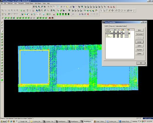
Figure 6 Polyline is created from points and placed on its own layer on the first of a series of identical openings
[/wptabcontent]
[wptabtitle] EXAMPLE[/wptabtitle]
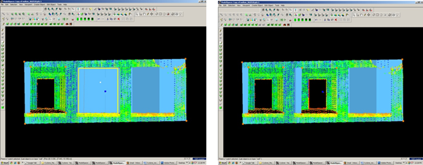
Figure 7 (Left) First opening has been subtracted from the primary patch and the polyline has been moved to the second proposed opening; (Right) Identical second opening has been subtracted
[/wptabcontent] [/wptabs]


