This workflow is intended for users with minimal AutoCAD experience who want to learn the basic navigation and file logic. As with any modeling program, there are many ways to perform each function and every user has different methods/shortcuts to reach the same goals. If you understand the concept and the priorities of the step, use the tools to your best advantage and find your own methods for completing tasks.
See AutoCAD’s help menu and the many free tutorials on-line to help with questions and steps. ACAD’s user interface is fairly friendly. Often just typing the command, all as one word without spaces, will either bring up the command or the appropriate help topic. Each new version of ACAD has changes in the interface but you can always access primary commands in this command line. Those new to the 2009 version of CAD may find the New Features Tutorial helpful.
Creating/Opening Files
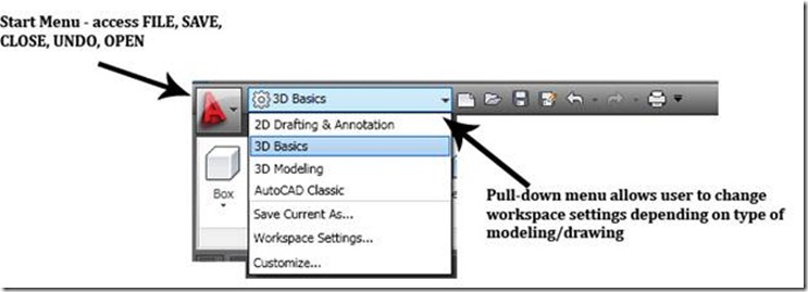
To Open an Existing File -> In ACAD -> Start Menu -> Open (see figure 1)
- When opening files from different versions of ACAD or containing different elements (such as an user-specific fonts or styles) a warning will appear when you open the file. If dialogue box asks for shape file (.shp) or states it cannot locate the shape file, close the box by clicking ‘X’ and the file will open, replacing the unknown file with a default replacement file.
- If a message appears regarding updating AEC elements, be aware that older versions of AutoCAD cannot read files saved in newer versions; in order to open/manipulate a new file in an old version of CAD –> Open the file in the NEW version of ACAD –> File –> Save As –> File Type –> pull down to select the appropriate version of CAD. See the information on file types .dwg versus .dxf in the overview ‘File Formats’.
To Create a New .DWG (ACAD drawing) -> Start Menu -> New -> Drawing -> Template Library opens -> to work with point clouds and other 3D work spaces choose “acad3D.dwt” -> template opens a 3D model space as a .DWG with a default file name -> adjust preferences as needed (see below) -> save file NOTE: The .dwt name varies w/ version of ACAD – the goal is choosing the 3D template)
Figure 1 ACAD’s start menu provides access to basic commands and types of modeling workspaces – user can move between Classic, 3D, and 2D work spaces or customize a new oneFile Formats
DWG – this is ACAD’s standard file format. The type of .DWG format varies with each different release/version of ACAD in which the file was saved (by year).
DXF – or “Drawing eXchange Format” is a format that is standardized in different CAD and graphics programs. This allows users to exchange drawings even if they don’t have the same program. When you use the DXF format, some objects may change their appearance when re-opened. See DXFOUT and DXFIN commands for exporting and importing DXF files, respectively.
NOTE: 2004.dxf is a highly supported/interchangeable format and will often allow exchange with other software which may not successfully allow the .DWG. To save an ACAD file as a .DXF -> file -> save as -> pull-down file type to .dxf
BAK – this is ACAD’s backup file format; ACAD automatically creates a duplicate backup file. If you original file becomes corrupt or un-usable, rename the BAK file to a DWG file and open as usual.
SV$ – This is AutoCAD’s format it uses whenever it performs an automatic save. AutoCAD will save the file automatically within a pre-determined time frame. Set the time frame and the location of automatic saves in Options > Files dialog box.
Navigation
There are several methods to navigate in ACAD
Command Line – simple commands such as PAN, ORBIT, ZOOM can be entered in the command line.
ZOOM – Use the zoom icon or the middle roller on your mouse to zoom in/out; also type ‘ZOOM’ in command line for zooming options. Type shortcut ‘ZE’ to zoom to the extents of all visible objects/points
Toolbars – Right click on the area where any visible toolbar is docked; this brings up your toolbar options. ACAD contains the most basic toolbars. Activating the toolbars for ‘Orbit’, ‘3D Navigation’, and ‘Views’ is recommended.
NOTE: When orbiting, a sphere is displayed with nodes shown on the top, bottom, left, and right – the cursor must be within this sphere (even if the objects/points are outside of it) in order to rotate/orbit; placing your cursor over the nodes helps control orbit; the objects and points are not visible during orbit but re-appear when the command ends
Mouse – by default the mouse is set to zoom in/out; RC also displays navigation options
Preferences/ Setup
UNITS – one of the most important preference to consider is units -> Command line -> UNITS -> Insertion Scale -> Set unit (maintaining the same unit as the scan data, which is usually meters, is recommended)
NOTE: If point cloud data and CAD need to be in different units or coordinate systems, use ACAD’s point cloud dialogue box to define units and coordinates as they will be used in ACAD -> Command Line -> POINTCLOUD -> Locate data -> Define units/coordinates -> data is converted to the scale/coordinates of the ACAD drawing
Other Preferences -> Command line –> ‘PREFERENCES’
Files –> displays and allows you to edit paths for file saves (including auto saves), backups, etc
Display –> Screen & element colors, crosshair size, & display performance
Open & Save –> Automatic Save setting options (set to 10 minutes between automatic backup/autosave by default; this can be an invaluable backup or it can be a frustrating time consumer – adjust this setting as needed based on file size and backup issues)
Explore other preferences and file options
Command Lines & Help Menu – Tips
Entering basic commands in their entirety or abbreviated into the command line is often successful and quick — ZOOM (Z), PAN (P), ORBIT, LINE (L), UNDO (U), SAVEAS; You can scroll through the command history with the up arrow in the command line or by entering ‘F2’
Snap Icons – Directly below the command line, Snap icons allow quick toggling of drawing constraints used during modeling
Figure 2 Active command line is highlighted in yellow; the user can scroll through the command history located directly above the active line; Snap icons are located directly below the command prompt; Also note that the Model and Layout tabs at the top allow user to move between model space and paper space
Help – ACAD has strong help/search capabilities so when in question, a good place to start is the help menu accessed through -> command prompt –> HELP or File –> Help or F1 Key or Typing keyword or phrase in search box located in upper right hand side of screen
Model Space, Paper Space, & Viewports
These are the names for the virtual spaces within ACAD. They are controlled through the layout tabs
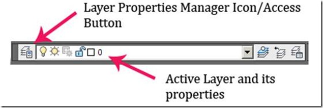
Figure 3 Layers Toolbar – LC on icon to open layer manager
Model Space = infinite 3D modeling space at 1:1 scale
**It is extremely important that from the very first step, you utilize the coordinate system in CAD. CAD is made up of infinite space and in order to keep your project organized, understanding this infinite space is essential. By default, every ModelSpace has the same origin point located at 0,0,0 (meaning the x, y, z coordinates are all at 0 – enter this value into the command line with no spaces). Recognizing and using the origin maintains a point of reference among various drawings. See the ‘Copying & Pasting Objects’ section below.
Layout/Paper Space = Virtual sheet of paper containing windows (or “viewports”) into model space. Layout/Paper space can be scaled, labeled, and manipulated without affecting the objects in model space. Layout is the preferred space from which to print/plot.
- Each layout is an individual “sheet of paper” containing an infinite number of viewports, labels, and text
- elements & layers can be viewed independently between model & paper space by adjusting their visibility in the Layers Manager
Viewports = a 2d view used to project the 3d model space into the layout view. It is similar to a ‘window’ that you place in paper space to look into Model Space.
Osnaps / Constraints
Osnaps and constraints are essential to utilizing the full accuracy and proficiency of ACAD. Icons to toggle them on/off are located along the bottom of the screen, below the command line (see figure 2)
Osnaps – when ON, they allow the user to “snap” drawing, modeling, and measurement tools to specific points on objects and point clouds (these points such as midpoint or end point appear when the cursor hovers above the location on the object). When OFF, these grips are not highlighted while drawing.
Infer Constraints – infers where objects, lines, or references would continue into space, allowing the user to snap to intersections/points that might not literally exist
Ortho Mode – restricts the user to orthogonal modeling/drawing
Polar Tracking – User can set a degree as a guide for modeling/drawing
Layers
Layers are the primary means of controlling objects in ACAD; organized, clearly-named layers are essential to managing the drawing.
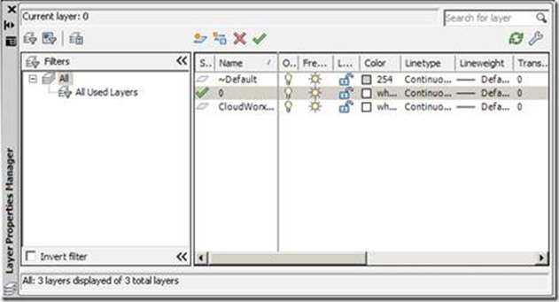
Note if importing data from Leica Cyclone: When a point cloud is loaded into CloudWorx, Cyclone’s layers are transferred into ACAD layers (Cyclone names transfer preceded by “~”). Unless you have changed layer names in Cyclone, the point cloud is on “~Default” upon import.
Create new layer(s) for all modeling work through the Layer Property Manager To create/manage layers -> RC on any ACAD toolbar -> LC Layers -> On Layers toolbar, LC Layer Property Manager icon (see Figure 4)
Figure 4 Layer Property Manager – Create and modify layers here. Layers are the primary means of controlling objects in ACAD and organized, clearly-named layers are essential to managing the drawing.
Selecting Objects
Lines, blocks, solids, and other objects can be selected individually or in groups/sets.
Select Single Object > LC directly on the object. It’s grips will highlight showing it has been selected > Use Shift + LC to select multiple grips
One or more objects > LC + move with the mouse to draw a selection window
- If the selection window is drawn from left-to-right, only objects that are COMPLETELY ENCLOSED BY THE WINDOW are selected
- If the window is drawn from right-to-left, every object that TOUCHES THE WINDOW is selected
De-select > LC + Re-selecting an object will de-select it from a set; ESCAPE will de-select the entire selection
 Figure 5 – (Left) Selection Window drawn left-to-right with start and end points marked. (Right) The grips (blue “dots”) of all objects selected are highlighted – Note the yellow rectangle in the lower right hand of the screen; although the selection window touched the rectangle, it did not enclose it, therefore it is not selected
Figure 6 – (Left) Selection Window drawn right-to-left with start and end points marked. (Right) The grips (blue “dots”) of all objects selected are highlighted – Again, note the yellow rectangle in the lower right hand of the screen; the selection window touched the box, therefore it is selected
Copying & Pasting Objects
Objects may be copied and pasted within a single drawing or copied from one drawing and pasted into another. In all cases, when objects are copied a base point is assigned. This base point is the “handle” of the copied object – you might think of it as the point at which the mouse is “holding onto” the object.
I. Copying Object(s) – clipboard
A. Select the object(s) to be copied
B. RC > Clipboard > Copy Options:
Copy = Objects are copied to the clipboard and a default base point is assigned; this base point’s location depends on how the object was created but it is often located in the lower left-hand corner of the object(s)
Copy with base point = Objects are copied to the clipboard and the user assigns the base point, which is useful when placing the object accurately
Assigning a base point – the base point may be assigned to a point on the object or to a point in the coordinate system. Using a point on the object is useful when you are trying to place objects and the coordinate system is not important. Using the coordinate system origin (0,0,0) is useful when copying object(s) from one coordinate system to another or when objects do not provide accurate references.
Point on Object > LC on a point on the object to specify it as the base point
Point in Coordinate System > When prompted to specify a base point, manually enter coordinates in the command line (#,#,# – digits separated by commas and NO spaces) > ENTER
NOTE: Copying by the origin point 0, 0, 0 (x=0, y=o, z=0) allows the user to paste by the same origin point; in this way, object(s) can be copied from one DWG and can be pasted into the exact same location in a different DWG regardless of differing scales or coordinate systems
II. Pasting Object(s) – clipboard
A. Paste by base point on the object(s) > RC > Clipboard > Paste > LC to place the object – the point that you LC represents the location that the base point of the copied object is placed
B. Paste by coordinates > RC > Clipboard > Paste options:
Paste to original coordinates = object is placed at the x, y, z coordinates of the original drawing that were defined as the base point by the user when the object was copied
Paste = Command line prompts for insertion point:
Enter coordinates in the command line (#,#,# – digits separated by commas and NO spaces) > ENTER
LC at point in new drawing > object(s) are placed according to the point that you specified as the base point in the original drawing with this LC
C. Paste as Block > Object(s) are converted into a single block/entity upon pasting; this is useful when copying complex drawings to keep everything together
NOTE: Blocks are groups or components that exist within a single drawing or multiple drawings. When copied or inserted, they retain the characteristics of the original block and when pasted, the block is placed on whatever layer is current; when one block is edited, all blocks are edited simultaneously.
NOTE: <EXPLODE> separates blocks into the individual, original objects (and their individual layers); when copying/placing multiple objects at the same time, pasting them as blocks helps to keep multiple objects grouped and positioned correctly until they are adjusted/placed, at which point they can be exploded
III. Copying/pasting within a single drawing – command line
A. Select the object(s) to be copied > command line: <CO> or <COPY>
B. Object is copied and remains visible and command line prompts the user to specify the base point > LC on a point on the original object to specify the base point
C. Dragging the mouse, moves the object to the point where the copied object is to be placed > LC on the point you want to paste the base point of the object


