These tutorials will show you how to digitize archaeological features from terrestrial scan data.
Hint: You can click on any image to see a larger version.
Before beginning a digitizing project in Rapidform consider what final products are required. Archaeological projects might require…
[/wptabcontent]
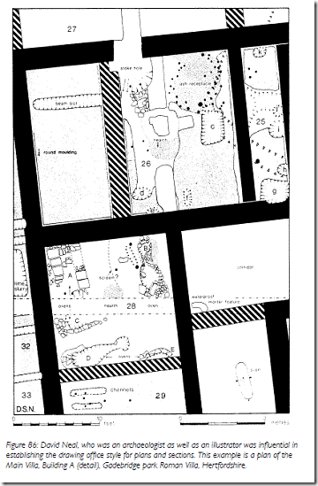
[wptabtitle] A 2D TECHNICAL ELEVATION OR PLAN[/wptabtitle] [wptabcontent]A 2D technical elevation or plan.
Technical elevations and plans utilize standardized conventions to represent 3D objects in 2D and include both metrical information and annotations. The multi-phase plan familiar from excavation is a classic example of technical drawing in archaeology.
Fig. 1: A 2D site plan (Image credit: Dobie and Evans 2010, p. 59, fig. 86)[/wptabcontent]
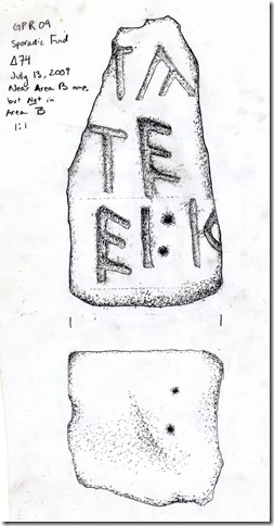
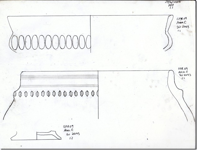
[wptabtitle] AN INTERPRETIVE DRAWING[/wptabtitle] [wptabcontent]An interpretive drawing.
An interpretive drawing is a representation of what the object, feature or structure looks like, emphasizing the salient aspects of the object which make it recognizable rather than metrics.
Fig. 2: An interpretive drawing of an inscription (top) and a vessel (bottom) from Gabii, Italy. (Image Credit: Katie Huntley, Gabii Project)[/wptabcontent]
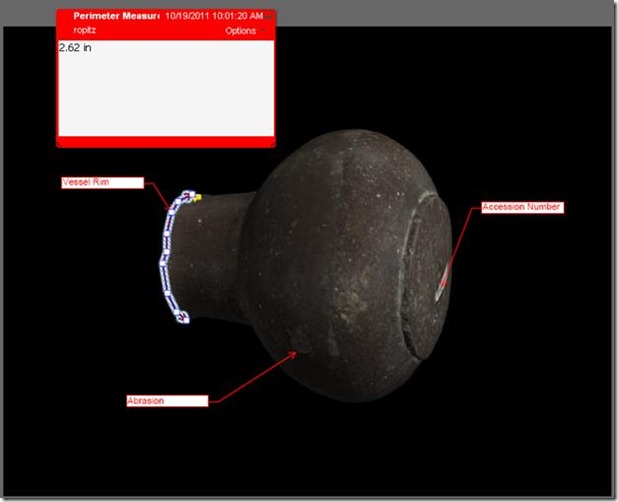
[wptabtitle] AN ANNOTATED 3D MODEL[/wptabtitle] [wptabcontent]An annotated 3D model.
Rather than creating a simplified vectorized model of 3D scan data, annotations and measurements are placed directly onto the scan data. The scan data is cleaned but remains undifferentiated in either a point cloud or mesh format.
Fig. 3: 3d model of vessel from scan data, with user annotations added. (Image Credit: CAST, Virtual Hampson Museum, http://hampson.cast.uark.edu/)
Annotations on scan data can indicate interpretations, like the presence of abrasions, or measurements, or vector overlays on salient features.[/wptabcontent]
[wptabtitle] AN ANNOTATED 3D INTERPRETIVE MODEL[/wptabtitle] [wptabcontent]An annotated 3D interpretive model.
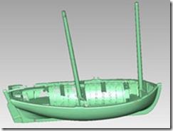
An interpretive 3D model is analogous to the 2D technical plan. It uses breaklines and solids to represent the form of the object and can include annotations and metrical information. Normally it will not include the original scan or mesh data.
Fig. 4: A solid model generated from scan data with individual features such as planks rendered as discrete objects. (Image credit: Traditional boats of Ireland Project, http://tradboats.ie/project/)[/wptabcontent]
[wptabtitle] THE DIGITIZING WORKFLOW[/wptabtitle] [wptabcontent]The digitizing workflow for each of these final products will be slightly different. This workflow covers the steps for the creation of an annotated 3D model.
[/wptabcontent]
[wptabtitle] CONTINUE TO…[/wptabtitle] [wptabcontent]Continue to step one of a digitizing project.[/wptabcontent] [/wptabs]
