This workflow will guide you through the process of digitizing archeological features from scan data using Rapidform.
Hint: You can click on any image to see a larger version.
General Considerations
Automatic feature recognition has improved greatly (and continues to improve) but isn’t quite up to most archaeological scenarios just yet. It follows that hand drawing, or ‘digitizing’, individual stones, patches of conservation materials, layers of mortar, etc. on scan data is part of many a project’s workflow. For information on drawing 3D vectors on scan data see Part 1 of the Rapidform GMV series.
For purposes of paper publications, sometimes it is convenient to produce a 2D rendering of a 3D object or feature. In archaeology sections, profiles, plans and elevation drawings are commonly used 2D renderings. The 3D vectors characterized from scan data can be converted into 2D drawings. When a 3D dataset is converted to a 2D plan drawing conventions (e.g. line styles, shadings, and hatchings) become essential for conveying information. Conversion is therefore a two-step process; first accurate 2D projections of the 3D vectors describing the feature or object are created, then appropriate drawing conventions are applied. The first stage is easily achieved in Rapidform. The second stage is better accomplished within a CAD, GIS or illustration program which provides finer control over the line artwork.
[wptabs style=”wpui-alma” mode=”vertical”]
[wptabtitle] OPEN A PROJECT[/wptabtitle]
[wptabcontent]Basic Workflow to create a 2D plan from existing 3D vectors in Rapidform
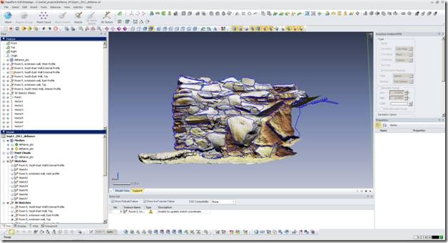
1. Open a project containing your scan data and 3D vectors.
Fig. 1: A Rapidform project with 3D vectors outlining individual stones in a wall.
[/wptabcontent]
[wptabtitle] CREATING A REFERENCE PLANE 1[/wptabtitle] [wptabcontent]
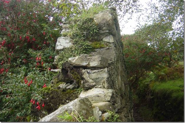
2. Create a reference plane where you want your 2D vectors to appear. Many archaeological features don’t have an obvious, neatly planar ‘top’ or ‘front’ face. Try to orient the reference plane parallel to the main orientation of the feature you are drawing. When choosing the orientation, you may want to consider placing perpendicular reference planes for the creation of a top plan or another elevation or section at the same time.
Fig. 2: This wall is substantially vertical but the front face, as seen from the path, is clearly not a flat plane.
[/wptabcontent]
[wptabtitle] CREATING A REFERENCE PLANE 2[/wptabtitle] [wptabcontent]
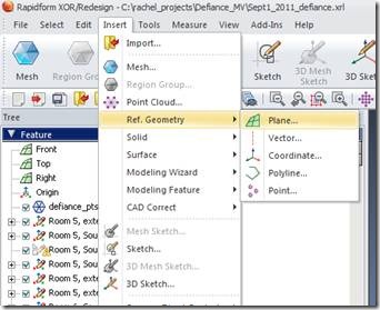
a. From the main menu, select “Insert” and from the dropdown menus select “Ref. Geometry” and then “Plane”.
Fig. 3: Select Insert Reference Plane.
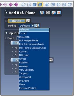
b. In the Add Ref. Plane menu a number of options are available for creating the plane. For the creation of an initial plane oriented in line with a set of features, the “Extract” option may be the simplest choice.
Fig. 4: Select a method for defining the reference plane.
[/wptabcontent]
[wptabtitle] CREATING A REFERENCE PLANE 3[/wptabtitle] [wptabcontent]
c. Select the entities you wish to include in the plan by left-clicking and sweeping the mouse across the entities.
Hint: Remember that the middle button on the mouse toggles between navigation and selection. ![]()
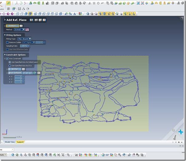
Fig. 5: Select options within the Add. Ref Plane menu.
d. In the Add Ref. Plane menu under Fitting Options set the Fitting Type to “Max. Bound” to create a plane surrounding all the selected entities.
e. Under Constraint Options select Axis Constraint and Use Specified Axis As Initial Guess. Then Select User Defined and choose the axis parallel to the long side of the reference plane you are creating. In the example in Fig. 5 this is the x-axis.[/wptabcontent]
[wptabtitle] CREATING A REFERENCE PLANE 4[/wptabtitle] [wptabcontent]
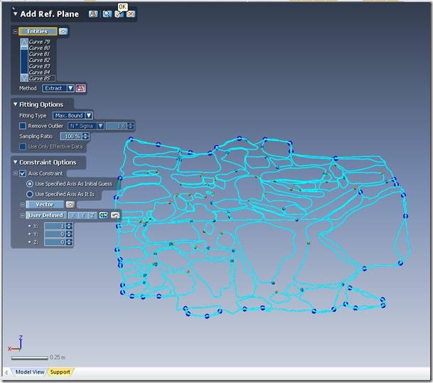
f. Click “OK” to create the Reference Plane.
Fig. 6: Click “OK” to accept the settings and create the Reference Plane.
[/wptabcontent]
[wptabtitle] EXPAND REFERENCE PLANE IF NECESSARY[/wptabtitle] [wptabcontent]
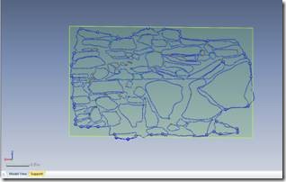
3. (optional) If the resulting Reference Plane does not entirely enclose the entities, you likely need to expand it.
Fig. 7: The Reference Plane does not entirely enclose the entities.
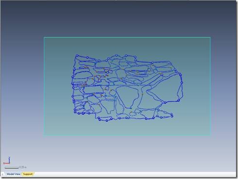
a. In the Add Ref. Plane menu select the Convert option for defining a plane. Then select the Reference Plane you just created. Click “OK” and a larger plane will be defined.
Fig. 8: The final reference plane should fully enclose all the features you are including in the plan.[/wptabcontent]
[wptabtitle] CREATE ORTHOGONAL REFERENCE PLANE 1[/wptabtitle]
[wptabcontent]
4. (optional) Create Orthogonal Reference planes for further plans.
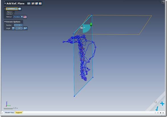
a. In the Add Ref. Plane menu select the Rotation option. Select the Plane you just created. This is the object which will be rotated. Select an entity, such as a polyline as the axis of rotation. Set the rotational Angle to 90 degrees. Click “OK” to create a new reference plane.
Hint: It may be useful to sketch a rectangle around the Reference Plane to create straight polylines for use as rotational axes.
Fig. 9: The Rotational method of creating a Reference Plane.
[/wptabcontent]
[wptabtitle] CREATE ORTHOGONAL REFERENCE PLANE 2[/wptabtitle] [wptabcontent]
b. Enter Sketch mode by selecting “Sketch” from the main toolbar.
Fig. 10: The Sketch button on the Main menu.
c. In the Sketch menu select the Rectangle tool. Select the Reference Plane just created as the Base Plane.
d. Draw a Rectangle over the area where you want to create the next Reference Plane. Click “OK” to accept the rectangle.
Fig. 11: The Rectangle tool in the Sketch toolbar.
[/wptabcontent]
[wptabtitle] CREATE ORTHOGONAL REFERENCE PLANE 3[/wptabtitle] [wptabcontent]
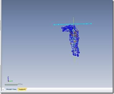
e. The rectangle should be nicely perpendicular to the first Reference Plane you created.
Fig. 12: The rectangle is perpendicular to the first Reference Plane.
f. Return to the Add Ref. Plane menu and select the Convert option. Select the Rectangle just created and click “OK” to create the Reference Plane.
Hint: Delete the intermediate planes after you have created the final Reference Planes.
[/wptabcontent]
[wptabtitle] PROJECT 3D SKETCHES ONTO PLANES[/wptabtitle] [wptabcontent]
5. Once the Reference Planes are prepared you can project 3D sketches onto those planes.
a. From the Main Menu enter Sketch mode.
b. Set the Base Plane to the Reference Plane on which you wish to project features.
c. Select the Convert Entities button from the Sketch Menu.
Fig. 13: The Convert Entities button.
d. Select the entities you wish to project onto the reference plane by holding down the left mouse button and sweeping across them. Click “OK” to convert the entities from 3D to a 2D projection.
[/wptabcontent]
[wptabtitle] PROJECT 3D SKETCHES – CONT.[/wptabtitle] [wptabcontent]
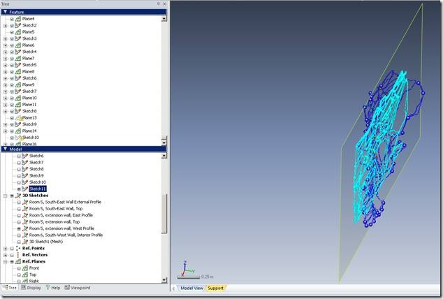
e. The features you selected should now appear as a 2D sketch listed in the Sketches menu on the left side of the screen.
Fig. 14: The 2D projection of the 3D vectors appears on the Reference Plane and in the Sketches list.
[/wptabcontent]
[wptabtitle] EXPORT[/wptabtitle] [wptabcontent]
6. The 2D sketch can now be exported for annotation and manipulation in a CAD, GIS or Illustration program.
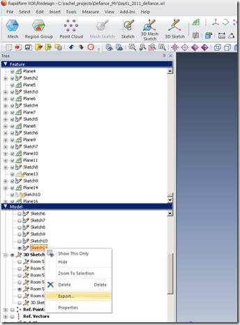
a. Right-click on the sketch in the Sketch list and select Export. Select the output format, .dxf is probably a good option.
Fig. 15: Export the Sketch.
b. Applying drawing conventions is not covered in the Rapidform tutorials. Be aware of regional (and even project to project!) variations in drawing conventions. We refer you to Approaches to Archaeological Illustration: A Handbook (Ed. Steiner, M., 2005, Council for British Archaeology and Association of Archaeological Illustrators and Surveyors).
[/wptabcontent] [/wptabs]
