This series will show you how create a mesh and model surface topography in Leica’s Cyclone
Hint: You can click on any image to see a larger version.
[wptabs style=”wpui-alma” mode=”vertical”] [wptabtitle] INTRODUCTION AND DEFINITIONS[/wptabtitle]
[wptabcontent]In this guide, a mesh is considered to be a series of triangles that represents a surface. Cyclone generates meshes by using the points in a point cloud, vertices, polylines, or any combination of the three as vertices. For each adjacent trio of points in a cloud, a triangle is created. This has the effect of creating a visually coherent surface from the point cloud, and it is the primary method for modeling topography.
Break lines are lines or polylines that sub-divide the mesh; they represent the edges of a paved surface, a ridge, a channel, or any other topographic feature that the user wants to preserve. While mentioned in 2D topographic tracing, break lines become very important in meshing. Here, they have an accurate z-coordinate and they become the edges that the triangles in the mesh conform to, defining and controlling the smoothness and continuity of the mesh. They allow the user to break-up the mesh into reasonable “chunks” for future texturing and detailing.
Please see ‘Leica Cyclone – Creating a Basic CAD Ojects From Surface Topography (2D)’ as a supplement to this workflow.[/wptabcontent]
[wptabtitle] OPEN A REGISTERED UNIFIED MODEL SPACE[/wptabtitle]
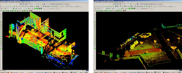
[wptabcontent]1. Open a Registered Unified Model Space -> Create fence around ground plane –> Right Click –> Copy Fenced to new Model Space (NOTE: viewing from a standard side, front, or back view in orthographic mode assists in selection) -> Original MS may be closed
Figure 1 – (Left) Original registered scan world of plaza (Right) Point Cloud Sub-Selection (Select -> Right Click -> Point Cloud Sub-Selection) allows unneeded points, such as trees and vertical surfaces, to be deleted; Sub-selection allows the user to precisely choose and view points before deciding to delete[/wptabcontent]
[wptabtitle] SELECT AND DELETE UNNEEDED POINTS[/wptabtitle]
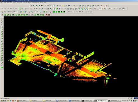
[wptabcontent]2. In the new Working MS -> Select and delete unneeded points (it’s best to eliminate as much vertical surface data as possible so that the ground plane to be modeled is isolated; objects in motion, such as trees/vegetation can be especially problematic and cleaning up areas where these are abundant is suggested; eliminating data that may be present inside buildings or areas that will not be modeled is also suggested)
Figure 2 – The same plaza as Figure 1 now copied to a working MS and “cleaned” of unneeded vertical surfaces and vegetation leaving only the ground plane to be modeled.[/wptabcontent]
[wptabtitle] CREATE NEW LAYERS FOR THE BREAKLINES AND FEATURES[/wptabtitle]
[wptabcontent]
3. Create new layers for the breaklines and features (Shift + L) -> Review the area to be modeled identifying where the surface changes and/or where the user wants a clean break or difference between adjacent surfaces.Create layers for primary and secondary features as needed.
4. Create lines to represent the topography and features, assigning an accurate x, y, and z coordinate -> There are several ways to make lines including (1) using 2D drawing methods (covered in ‘Topography and Site Elements – 2D’ above) (2) with pick points, (3) by extending an existing line (4) by snapping two existing lines together (5) by creating a polyline with Fit Edge command, and (6) by merging polylines together.
See Help -> Contents -> Search -> ‘Make Lines, Polylines, and Breaklines’ for steps for each of these methods.There are additional variations of each.BEWARE: Lines created by pick points cannot be used for break lines in meshing; if picking points, be sure to create a polyline rather than a line segment.[/wptabcontent]
[wptabtitle] TIPS[/wptabtitle]
[wptabcontent]5. Tips
A. If drawn in 2D, use Edit Object -> Move/Rotate to move the object to the correct z-coordinate; there are multiple options moving objects including by a standard axis and pick points.
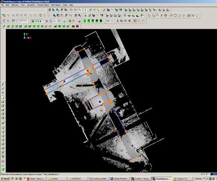
B. Create additional break lines following the feature or edge of the break lines; place these to break up the mesh and around the boundaries, segmenting out areas where a topographic ground plane is not needed (ie: inside buildings)
Figure 3 – Top view of plaza; Polylines have been created to outline where the sidewalk and grass meet; orange handles help highlight the polylines
[/wptabcontent]
[wptabtitle] MORE TIPS[/wptabtitle]
[wptabcontent]More Tips:
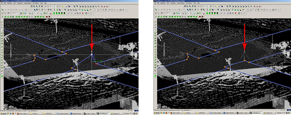
C. Use multiple views to confirm line is properly located at all angles and handle constraints (Edit Object -> Handles constrain to -> Various options – NOTE: once placed in top view, constraining handles to z-direction helps placement in 3D)
D. Try different methods to see what works for you.With all, use multiple views to confirm the line is properly located at all angles
Figure 4 – (Left) Although from Top View, the breakline looks correct, inspection from a different angle reveals that it is not correct (Right) Handles and constraints (Edit Object -> Handles -> Constrain Motion) are used to pull the polyline into the correct position – every section of every breakline should be inspected from multiple views
[/wptabcontent]
[wptabtitle] FINAL STEPS[/wptabtitle] [wptabcontent]6. Create handles at places where polylines intersect (Select line -> ALT + Select point on line for new handle to help snap lines together).
7. Delete all points beyond boundary of mesh -> Select polyline representing boudary of mesh -> Right click -> Fence -> From Selection -> Fence -> Delete outside
8. Delete points within other breaklines to remove any remaining points that should not be considered in the creation of the mesh -> Copy final breaklines to original or temporary working space in case altered/needed in future
8. Unify points reducing spacing to 1 foot to start and adjust settings for desired results.[/wptabcontent]
[wptabtitle]CONTINUE TO…[/wptabtitle]
[wptabcontent]Continue to Creating the Topographic Mesh[/wptabcontent][/wptabs]


