This document will introduce you to the inferface basics of Polyworks.
Hint: You can click on any image to see a larger version.
[wptabs style=”wpui-alma” mode=”vertical”] [wptabtitle] INTRODUCTION TO WORKSPACE MANAGER[/wptabtitle]
[wptabcontent]
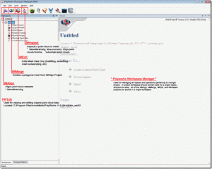
Polyworks is a modularized package that offers a centralized workspace for organizing component parts of 3D data processing from scan alignment to meshing to inspection. Users can access any of the main modules from the Polyworks Workspace Manager as well as individually from the Start Menu. The principal modules and their functionality are listed in Figure 1 below:
Figure 1: Polyworks Workspace Manager showing principal software modules
The Polyworks Workspace is meant to house all processing components related to a project. Therefore it is best to create workspaces that are specific to a given project. For example with object scanning projects where multiple objects of a collection are scanned and process, a workspace should ideally be created for each individual object.
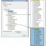
When a Polyworks Workspace is saved, a .pwk file is created (sample.pwk) along with an associated workspace file structure (sample_Files). The associated file structure (shown in Figure 2 below) manages all of the projects from the internal modules (IMAlign, IMEdit, etc…) as well as the data imported and exported from those modules.
Figure 2: Polyworks Workspace file (PWK) and additional workspace files
When moving files from one location to another, it is recommended to first zip a workspace to ensure that the workspace data structure and organization are retained. For more on the Polyworks Workspace Manager, please reference the Workspace Manger Basics.pdf from the Help menu in Polyworks.[/wptabcontent]
[wptabtitle] DESCRIPTION OF PRIMARY MODULES[/wptabtitle] [wptabcontent]
IMAlign
IMAlign supports scan alignment of 3D digitized datasets. IMAlign offers direct interaction with a list of different digitizers as well as import support for a range of point cloud and mesh formats. Here users can align different datasets and prepare them for subsequent meshing.
Figure 3: List of import formats for IMAlign
IMMerge
IMMerge is the meshing utility of Polyworks that produces a polygonal model directly from an IMAlign project. Note – Only point clouds can be meshed in IMMerge.
IMEdit
IMEdit is the mesh editing module of Polyworks. Here a number of mesh cleanup operations are available including hole filling and smoothing. Curve Creation and NURBS Surfacing options are also available in IMEdit.
IMInspect
IMInspect offers product inspection, measurement, and comparison capabilities. Here users can import original 3D point clouds, polygonal meshes, and CAD datasets and perform a range of different measurements and comparisons. Primitive fitting as well as feature extraction is performed in IMInspect.[/wptabcontent]
[wptabtitle] DESCRIPTION OF LESSER MODULES[/wptabtitle] [wptabcontent]
IMCompress
IMCompress is a module completely dedicated to model reduction or decimation. The same capabilities are available from inside IMEdit.
IMTexture (Add-On)
IMTexture is an optional module available that generates texture maps from vertex colors for reduced models. It is currently available from Innovmetric for – Academic pricing.
IMView
IMView is the free viewing software provided by Innovmetric. It is available in the main product sweet and also standalone from the Innovmetric website.
IMKey
IMKey is the licensing utility for the entire Polyworks suite. License borrowing capabilities are available here.[/wptabcontent]
[wptabtitle] MOUSE BUTTON FUNCTIONALITY[/wptabtitle] [wptabcontent]
Polyworks Mouse Button Functionality
| Left: Rotate | Shift + Middle: Boxed Zoom In |
| Middle: Pan | Shift + Right: Rotate about Viewing Axis |
| Right: Zoom |
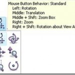
In addition to the basic mouse functionality listed above, there are also options for single button controls available in each of the modules. These controls are shown below in Figure 4.
Figure 4: Mouse Button Behavior Options in Polyworks modules[/wptabcontent]
[wptabtitle] SCENE DISPLAY OPTIONS[/wptabtitle] [wptabcontent]
Scene Display Options (all modules)
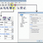
The main display options in Polyworks are available by clicking on two highlighted icons in Figure 5. These icons are available in all of the main modules and may vary slightly between the different modules.
Figure 5: (Left) Polyworks Viewing Options and (Right) Scene Options as shown in IMAlign
The object display ![]() options (shown bottom left in Figure 5 above) are covered here in more detail.
options (shown bottom left in Figure 5 above) are covered here in more detail.
Object color Mode
Point: Displays image texture data
Default: Displays all scans with default gray material
Object: Displays each scan with unique color
Image Subgroup: Displays each image subgroup with unique color
Error Map: Displays error map from best fit alignment (if option is selected during alignment
operation)
Default Static Display
Drawing Type
Flat: Displays as mesh data set with flat shading (allows you to see individual facets)
Point: Display as point cloud
Smooth: Displays as mesh data set with smooth shading
Wireframe: Displays wireframe of mesh
Subsampling
1/1
1/4: One point is displayed for every 4 points
1/16
1/64[/wptabcontent]
[wptabtitle] SELECTION TOOLS[/wptabtitle] [wptabcontent]
Selection Tools
The user activates selection in Polyworks by tapping the space bar. Tapping the space bar again also deactivates selection and switches to view manipulation/scene navigation.
To perform a selection the user must:
(Hold) Shift: Allows Volumetric Selection – necessary for selecting within point clouds
(Optional Hold) Ctrl: Allows Polygonal Outline of Selection.
No Ctrl: Freeform selection
(Hold) Middle Mouse button- to trace the selection
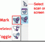
The Selection Menu shown in Figure 6 below is available in all PW modules. The default selection mode is set to toggle, therefore to append a selection or deselect – the user must change the selection mode to mark or deselect respectively.
Figure 6: Selection Modes in Polyworks[/wptabcontent]
[wptabtitle] SHORTCUT KEYS[/wptabtitle] [wptabcontent]
Shortcut Keys
| Keys | Function |
| Ctrl + Shft + A | Select All |
| Ctrl + Shft + D |
Hide Scans Can also middle click on scan name in TOC |
| Ctrl + Shft + R | Restore Scans |
| Ctrl + Shft + E | Ignore Scans (ignored for most operations) |
| Ctrl + Shft + U | Use Scans |
| Ctrl + Shft + K | Keep Scan (Keeps selected scan – hides all others) |
| Ctrl + Shft + L | Lock Scan |
| Ctrl + Shft + O | Unlock Scan |
[/wptabcontent]
[wptabtitle] IMALIGN BASICS[/wptabtitle] [wptabcontent]
IMAlign Basics (Getting Started)

Figure 7: Remember to set IMAlign options as suggested below prior to importing any data
IMAlign is the Polyworks module that allows you to import and align scan data. When you first open IMAlign, it’s good to define a couple of parameters.
Before you import any data, open IMAlign options and change the Digitizer from Generic Close Range to the scanner you are working with and change the working units to the digitizer units. Also, turn off the Interactive Mode Wizard and the Unknown Units Wizard. Also, under Alignment change Subsampling from 1/4 to 1/1 and under images, Max Angle choose 85. Next, go to Tools – Save Configuration (to save the new settings).
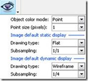
Figure 8: The highlighted icon controls how the scan data will be displayed in the scene.[/wptabcontent]
[wptabtitle] RECOMMENDED VIEWING OPTIONS[/wptabtitle] [wptabcontent]Below are the recommended settings for the Viewing Options
Object color Mode Recommended parameters are bolded/italicized
Point: Displays image texture data (Intensity (I) data for Optech; RGB data for Leica)
Default: Displays all scans with default gray material
Object: Displays each scan with unique color
Image Subgroup: Displays each image subgroup with unique color
Error Map: Displays error map from best fit alignment (if option is selected during alignment
operation)
Default Static Display Recommended parameters are bolded/italicized
Drawing Type
Flat: Displays as mesh data set with flat shading (allows you to see individual facets)
Point: Display as point cloud
Smooth: Displays as mesh data set with smooth shading
Wireframe: Displays wireframe of mesh
Subsampling
1/1
1/4 : One point is displayed for every 4 points
1/16
1/64
Default Dynamic Display (Recommended parameters bolded/italicized)
Drawing Type
Point
Subsampling
1/16 or 1/64
You are now ready to begin importing scan data into your IMAlign Project![/wptabcontent] [/wptabs]
