This series will show you advanced modeling building modeling techniques using Leica’s Cyclone.
Hint: You can click on any image to see a larger version.
As objects become more complex, using layers (Shift + L) becomes essential to organizing and controlling the model space.
[wptabs style=”wpui-alma” mode=”vertical”]
[wptabtitle]MODELING AN ANGLED WINDOW OPENING [/wptabtitle]
[wptabcontent]
A. Modeling a Complex Shape – An Angled Window Opening
- Copy area to be modeled into new, working ModelSpace
- Familiarize yourself with the object and the different layers/depths in space that you are working with; when angles are involved it’s good to understand where each angle terminates.
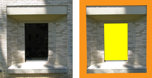
Figure 8 (Left) Complex window to be modeled (Right) Familiarize yourself with the layers of space to be modeled – here yellow represents the farthest plane (the glass) and orange represents the closest plane (the wall in which the window is set)
[/wptabcontent]
[wptabtitle]DIVIDE INTO SUB-SELECTIONS IF NESSCEARY[/wptabtitle]
[wptabcontent]
3. It may be useful to divide the point cloud into sub-selections based on their depth in space or on separate areas to model – Rotate the object to view it from the side or top view -> fence the area to be subselected -> RC -> Point Cloud Subselection -> Add Inside Fence
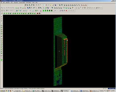
Figure 9 – Point cloud is sub-selected into several clouds based on their depth in space
[/wptabcontent]
[wptabtitle] MODEL THE OBJECT[/wptabtitle]
[wptabcontent]
4. Model the object using patches, extensions and extrusions as previously outlined – when modeling angled or complex surfaces, patches can be created several ways. When fencing an area and fitting a patch, fence the area that best represents the surface – exclude areas where the surface becomes skewed or extreme near boundaries, curves, etc.
5. While snapping adjacent patches together and extending them, extra handles are often created. It’s best to clean up the patches as you go of any extra handles/geometries to maintain simple, clean lines where possible: Select Patch -> ALT + RC on extra handle -> handle removed
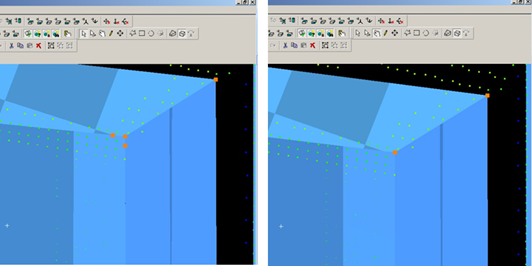 Figure 10 – (Left) Extra handles have been created where the patches intersect (Right) Extra handles deleted, leaving the cleanest, simplest geometry possible
[/wptabcontent]
[wptabtitle] MODELING TIPS[/wptabtitle] [wptabcontent]
6. As objects become more complex and angles become more complicated, it may be helpful to visually clarify and define the objects. This can be done several ways, including editing object colors and creating lines along the edges of objects that are intersecting. Lines create crisp edges and create wireframe objects for export later.
6A. Change Object Color -> Select Object -> Edit Object -> Appearance -> Choose color
6B. Creating Lines where objects intersect: Once the patches/objects have been extended to one another > Mult-select 2 intersecting patches -> Create Object -> From Intersections -> Curve (Note that in Cyclone, a curve here is a line. Also note that sometimes lines will extend beyond the object. Select the line -> slide the handles so beginning and end of line is within the object -> use handles or extend command to make the lines form corners) NOTE: It’s recommended to place lines/polylines on their own layer to aid in there selection and visibility later.
[/wptabcontent]
[wptabtitle] MORE MODELING TIPS[/wptabtitle] [wptabcontent]
7. While modeling complex objects, you will encounter areas where surfaces exist but there is no point cloud data to model directly from. Extruding and extending will often produce these surfaces but sometimes creating polylines and customized patches may be the best way to model these areas. Using the handles of previously modeled objects helps maintain the accuracy of the scan data.
7A. Align view to see the vertices of existing objects to use as guides for the edges of the proposed patch.
7B. Choose handles/points to create the new patch – select the points in the order you wish to draw the polyline that will define the edges for the patch. Do not close the polyline, leaving the last line segment open.
7C. Create Object -> From Pick Points -> Polyline -> Assign Polyline to its own layer
7D. Create Object -> From Curves -> Patch
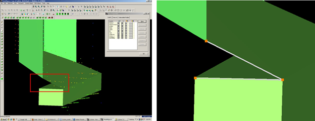
Figure 11 – (Left) Objects have been created from point cloud however no data exists for the area inside the red rectangle (Right) Handles of the previously modeled objects are used as pick points to
define the edges of the custom patch – note that the final side of the polygon is left open
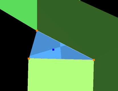
Figure 12 – Polyline that was formed from pick points is used to create new custom patch[/wptabcontent]
[wptabtitle] GROUPING[/wptabtitle] [wptabcontent]
Helpful Hints –
Grouping: Whether repeating a complex feature or using it only once, it’s a good idea to group the various objects together to maintain the integrity of the individual objects and their intersections. Both small and large ScanWorlds can be best controlled through:
(1) Copying specific areas to a new ModelSpace to model individually > Fence > RC > Copy to new MS
(2) Grouping complex features after they are modeled > Select All Objects that compose complex feature -> Edit -> Group
NOTE: Select all objects, NOT points in the grouping; Items may be ungrouped and removed from groups through the same command
[/wptabcontent]
[wptabtitle] HINT – VISIBILITY AND SELECTABLITLY[/wptabtitle] [wptabcontent]Hints
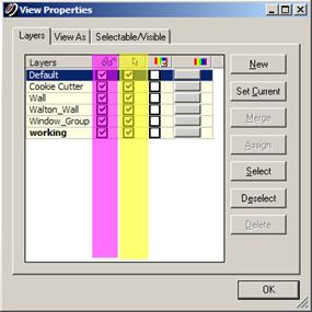
Visibility and Selectability – As complexity increases the use of layers becomes crucial. You can control which layers are visible and selectable in the layers dialogue box during an active command; this becomes very useful as points, objects, and lines become placed on top of one another)
Figure 13 – Magenta highlights the column showing whether layer is visible; yellow highlights the column showing whether layer is selectable – these attributes can be toggled as needed during active commands[/wptabcontent]
[wptabtitle] HINT – ACTIVE COMMAND[/wptabtitle] [wptabcontent]Hints
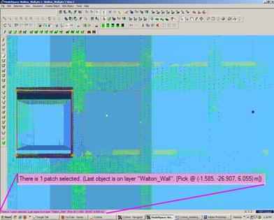
Active Command Dialogue – The command dialogue at the bottom of the screen is also very useful as models become more complex. It lists everything that is selected (line, point cloud, group, etc), and as each item is selected, the dialogue shows the layer of and the specific coordinates of each
Figure 14 – The dialogue line at the bottom, left of the screen shows information about the items that are actively selected.[/wptabcontent]
[wptabtitle] HINT – EXPLODE COMMAND[/wptabtitle] [wptabcontent]Hints
Explode Command – When a volumetric object is used or when a patch is exploded, it may be necessary to break the volume into individual planes –> Select Object -> Create Object -> Explode[/wptabcontent]
[wptabtitle]CONTINUE TO…[/wptabtitle]
[wptabcontent] Continue to Modeling and Placing Repeating Features [/wptabcontent] [/wptabs]
