[wptabs mode=”vertical”]
[wptabtitle] RGB Image[/wptabtitle]
[wptabcontent]The color image streaming from the RGB camera is much like that from your average webcam. It has a standard resolution of Height:640 Width:480 at a frame rate of 30 frames per second. You can “force” the Kinect to output a higher resolution image (1280×960) but it will significantly reduce it’s frame rate.
Many things can be done with the RGB data alone such as:
- Image or Video Capture
- Optical Flow Tracking
- Capturing data for textures of models
- Facial Recognition
- Motion Tracking
- And many more….
While it seems silly to purchase a Kinect (about $150) just to use it as a webcam – it is possible. In fact there are ways to hook the camera up to Microsoft’s DirectShow to use it with Skype and other webcam-enabled programs. (Check out this project http://www.e2esoft.cn/kinect/)
[/wptabcontent]
[wptabtitle] Depth Image[/wptabtitle]
[wptabcontent] The Kinect is suited with two pieces of hardware, which through their combined efforts, give us the “Depth Image”.
It is the Infrared projector with the CMOS IR “camera” that measures the “distance” from the sensor to the corresponding object off of which the Infrared light reflects.
I say “distance” because the depth sensor of the Kinect actually measures the time that the light takes to leave the sensor and to return to the camera. The returning signal to the Kinect can be altered by other factors including:
- The physical distance – the return of this light is dependent on it reflecting off of an object within the range of the Kinect (~1.2–3.5m)
- The surface – like other similar technology (range cameras, laser scanners, etc.) the surface which the IR beam hits affects the returning signal. Most commonly glossy or highly reflective, screens (TV,computer,etc.), and windows pose issues for receiving accurate readings from the sensor.
[/wptabcontent]
[wptabtitle] The IR Projector[/wptabtitle]
[wptabcontent]
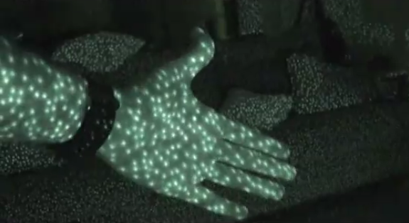
The IR projector does not emit uniform beams of light but instead relies on a “speckle pattern” according to the U.S. Patent (located here:http://www.freepatentsonline.com/7433024.pdf )
You can actually see the IRMap, as it’s called, using OpenNI. Here is a picture from Matthew Fisher’s website and another excellent resource on the Kinect (http://graphics.stanford.edu/~mdfisher/Kinect.html)
The algorithm used to compute the depth by the Kinect is derived from the difference between the speckle pattern that is observed and a reference pattern at a known depth.
“The depth computation algorithm is a region-growing stereo method that first finds anchor points using normalized correlation and then grows the solution outward from these anchor points using the assumption that the depth does not change much within a region.”
For a deeper discussion on the IR pattern from the Kinect check out this site : http://www.futurepicture.org/?p=116
[/wptabcontent]
[wptabtitle] Coordinate System[/wptabtitle]
[wptabcontent]
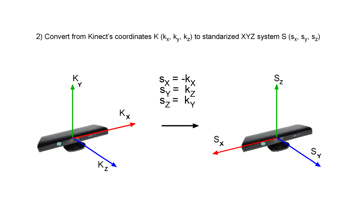
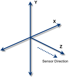
As one might assume the Kinect uses these “anchor points” as references in it’s own internal coordinate system. This origin coordinate system is shown here:
So the (x) is the to left of the sensor, (y) is up, and (z) is going out away from the sensor.

This is shown by the (Kx,Ky,Kz) in the above image, with the translated real world coordinates as (Sx,Sy,Sz).
The image is in meters (to millimeter precision).
[/wptabcontent]
[wptabtitle] Translating Depth & Coordinates[/wptabtitle]
[wptabcontent]
So when you work with the Depth Image and plan on using it to track, identify, or measure objects in real world coordinates you will have to translate the pixel coordinate to 3D space.OpenNI makes this easy by using their function (XnStatus xn::DepthGenerator::ConvertProjectiveToRealWorld) which converts a list of points from projective(internal Kinect) coordinates to real world coordinates.
Of course, you can go the other way too, taking real world coordinates to the projective using (XnStatus xn::DepthGenerator::ConvertRealWorldToProjective)
The depth feed from the sensor is 11-bits, therefore, it is capable of capturing a range of 2,048 values. In order to display this image in more 8-bit image structures you will have to convert the range of values into a 255 monochromatic scale. While it is possible to work with what is called the “raw” depth feed in some computer vision libraries(like OpenCV) most of the examples I’ve seen convert the raw depth feed in the same manner. That is to create a histogram from the raw data and to assign the corresponding depth value (from 0 to 2,048) to one of the 255 “bins” which will be the gray-scale value of black to white(0-255) in an 8-bit monochrome image.
You can look at the samples given by OpenNI to get the code, which can be seen in multiple programming languages by looking at their “Viewer” samples.
[/wptabcontent]
[wptabtitle] Accuracy[/wptabtitle]
[wptabcontent]
Another thing worth noting is the difference in accuracy of the depth image as distance from the Kinect increases. There seems to be a decrease in accuracy as one gets further away from the sensor, which makes sense when looking at the previous image of the pattern that the IR projector emits. The greater the physical distance between the object and the IR projector, the less coverage the speckle pattern has on that object in-between anchor points. Or in other words the dots are spaced further apart(x,y) as distance(z) is increased.
The Kinect comes factory calibrated and according to some sources, it isn’t that far off for most applications.
[/wptabcontent]
[wptabtitle] Links for Recalibrating[/wptabtitle]
[wptabcontent]
Here are some useful links to recalibrating the Kinect if you want to learn more:
- http://www.ros.org/news/2010/12/technical-information-on-kinect-calibration.html
- http://labs.manctl.com/rgbdemo/index.php/Documentation/TutorialProjectorKinectCalibration
- http://openkinect.org/wiki/Calibration
- http://nicolas.burrus.name/index.php/Research/KinectCalibration
- http://sourceforge.net/projects/kinectcalib/ (a MatLab ToolBox)
[/wptabcontent]
[wptabtitle] User Tracking[/wptabtitle]
[wptabcontent]
The Kinect comes with the capability to track users movements and to identify several joints of each user being tracked. The applications that this kind of readily accessible information can be applied to are plentiful. The basic capabilities of this feature, called “skeletal tracking”, have extended further for pose detection, movement prediction, etc.
According to information supplied to retailers, Kinect is capable of simultaneously tracking up to six people, including two active players, for motion analysis with a feature extraction of 20 joints per player. However,PrimeSense has stated that the number of people that the device can “see” (but not process as players) is only limited by how many will fit into the field-of-view of the camera.
An in depth explanation can be found on the patent application for the Kinect here:http://www.engadget.com/photos/microsofts-kinect-patent-application/
[/wptabcontent]
[wptabtitle] Point Cloud Data[/wptabtitle]
[wptabcontent]
The Kinect doesn’t actually capture a ‘point cloud’. Rather you can create one by utilizing the depth image that the IR sensor creates. Using the pixel coordinates and (z) values of this image you can transform the stream of data into a 3D “point cloud”. Using an RGB image feed and a depth map combined, it is possible to project the colored pixels into three dimensions and to create a textured point cloud.
Instead of using 2D graphics to make a depth or range image, we can apply that same data to actually position the “pixels” of the image plane to 3D space. This allows one to view objects from different angles and lighting conditions. One of the advantages of transforming data into a point cloud structure is that it provides for more robust analysis and for more dynamic use than the same data in the form of a 2D graphic.
Connecting this to the geospatial world can be analogous to the practice of extruding Digital Elevation Models (DEM’s) of surface features to three dimensions in order to better understand visibility relationships, slope, environmental dynamics, and distance relationships. While it is certainly possible to determine these things without creating a point cloud, the added ease of interpreting these various relationships from data in a 3D format is self-evident and inherent. Furthermore, the creation of a point cloud allows for an easy transition to creating 3D models that can be applied to various domains from gaming to planning applications.
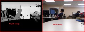
So with two captured images like this:
We can create a 3D point cloud.
[/wptabcontent]
[wptabtitle] Setting Up Your Development Environment[/wptabtitle]
[wptabcontent] We will give you a few examples on how to set up your Development Environment using Kinect API’s.
These are all going to be demonstrated on a Windows 7 64-bit machine using only the 32-bit versions of the downloads covered here.
At the time of this post the versions we will be using are:
OpenNI: v 1.5.2.23
Microsoft SDK: v 1.5
OpenKinect(libfreenect): Not Being Done at this time… Sorry
To use the following posts you need to have installed the above using these directions.
[/wptabcontent]
[/wptabs]


